boat temperature gauge wiring diagram
[DIAGRAM] Car Gas Gauge Diagram
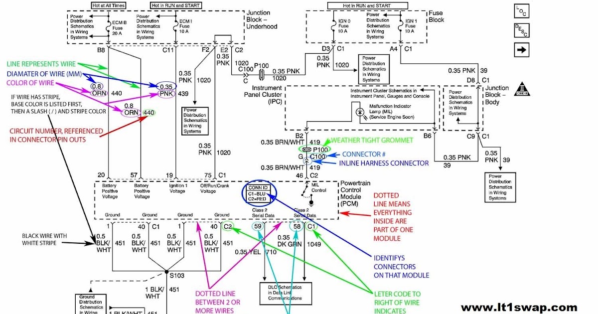
We're breaking down the basics of what's happening behind the dash on your console with your gauge wiring. It's not so scary once you understand how gauges are powered and supplied signal..

Wiring Diagram For Boat Gauges Wiring Digital and Schematic
Jump To Complete Diagram Download PDF Guide 1. The Electrical Source: a Battery In a boat, electricity is stored in one or more batteries. The batteries are charged by your engine's alternator or auxiliary battery charger.

Wiring Diagram For Alternator On A Boat Motor Roblox Redeem Stanley
AC Vs. DC On many boats there are two types of current: alternating (AC) and direct (DC). Serious damage and even electrocution can result from confusing the two. In recently built boats, the two systems should be clearly differentiated and separated, including at the electrical panel.

Faria Tachometer Wiring Diagram
Taking the time to properly wire a trim gauge can prevent a number of potential problems, while also providing an accurate reading of the angle of the boat's hull. Knowing how to wire a trim gauge is an important skill for any boat owner, and one that could potentially save lives. Trim Limit And Sender Club Sea Ray. Trim Sensor Volvo Penta.
Yamaha Boat Wiring Diagram Wiring Diagram Schemas
How to Install Faria Marine Gauges Using Wiring Diagrams Before starting, it's important to understand the basics of wiring diagrams. Wiring diagrams provide an easy way to show the connections necessary for installing Faria marine gauges. When following wiring diagrams, it's important to match the colors and terminals correctly to prevent.
Electric Fuel Gauge Wiring
Boat gauge wiring diagrams are used to map the electrical connections of your boat's components. These diagrams illustrate how the components are connected, how the wiring is routed, and what each wire is connected to. The diagrams can also show the power and ground wires and the signal wires.
Basic 12 Volt Boat Wiring Diagram Cadician's Blog
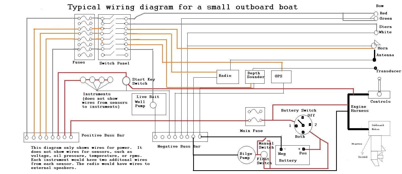
There are wiring diagrams, websites and forums that tell you how to wire an electrical system for large boats and bigger sailboats. But when it comes to small boats there is a distinct lack of information and diagrams for how to install a simple, safe, and reliable electrical system.
boat temperature gauge wiring diagram
By Gabriel Roy Posted on November 25, 2022 It might be challenging to install a gauge package on a Yamaha board since the wiring is so intricate. However, after learning the color codes, you encounter a Yamaha outboard gauge wiring diagram and find yourself utterly baffled as to how to actually mount one.

Wiring Diagram For Boat Gauges Wiring Digital and Schematic
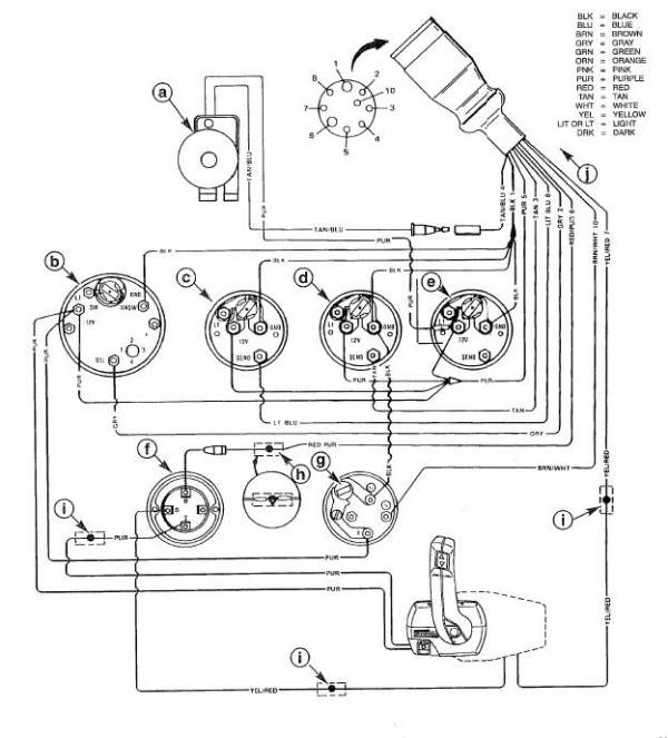
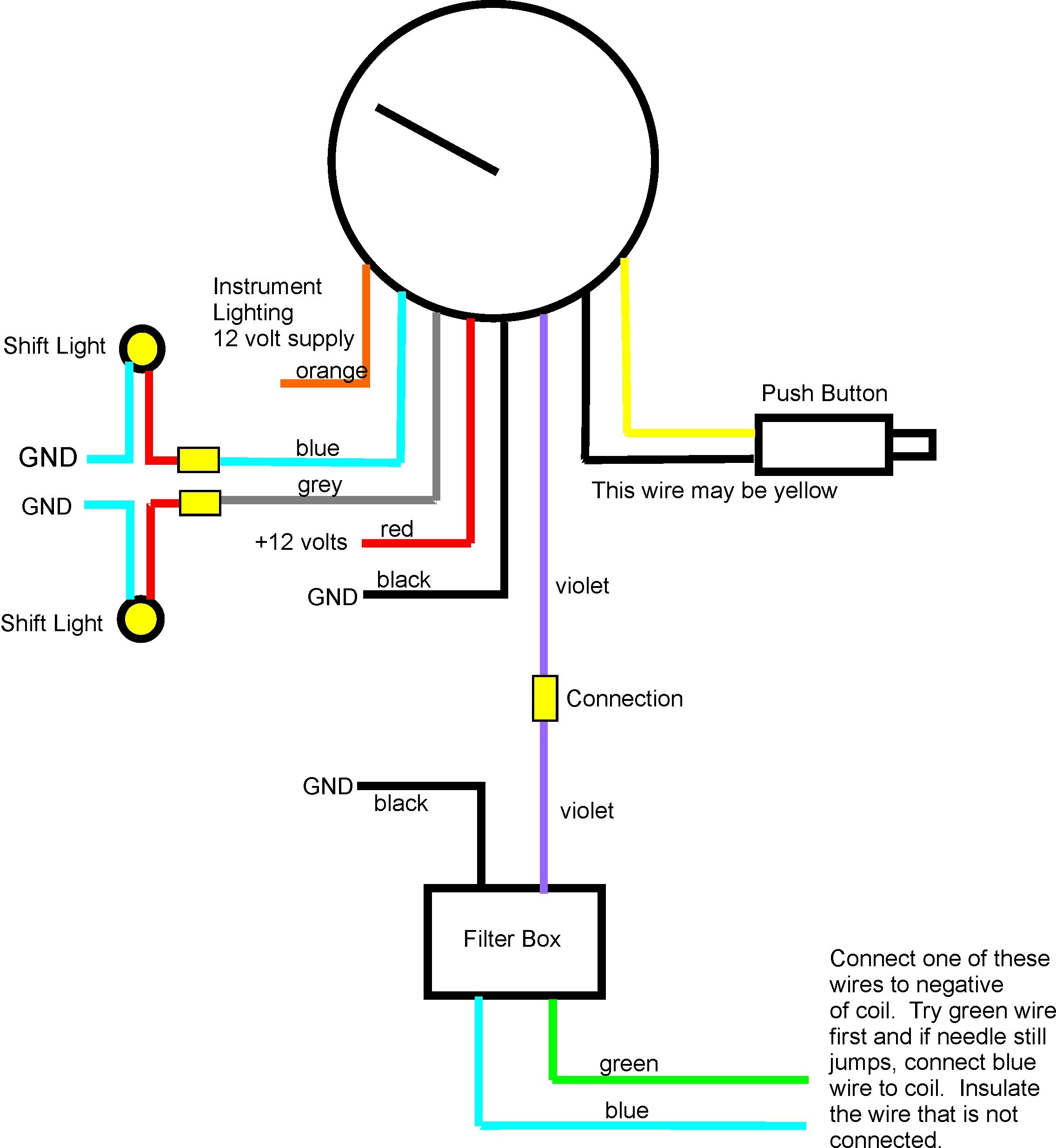
Figure 1. Tachometer terminals. Beginning with the tachometer, Fig. 1 here shows the back of a typical gauge. At the top left of the diagram, we see the cylinder selector switch. Most vendors will use one tachometer head to cover a variety of engines. Make sure this switch is set to the number of cylinders for your engine.
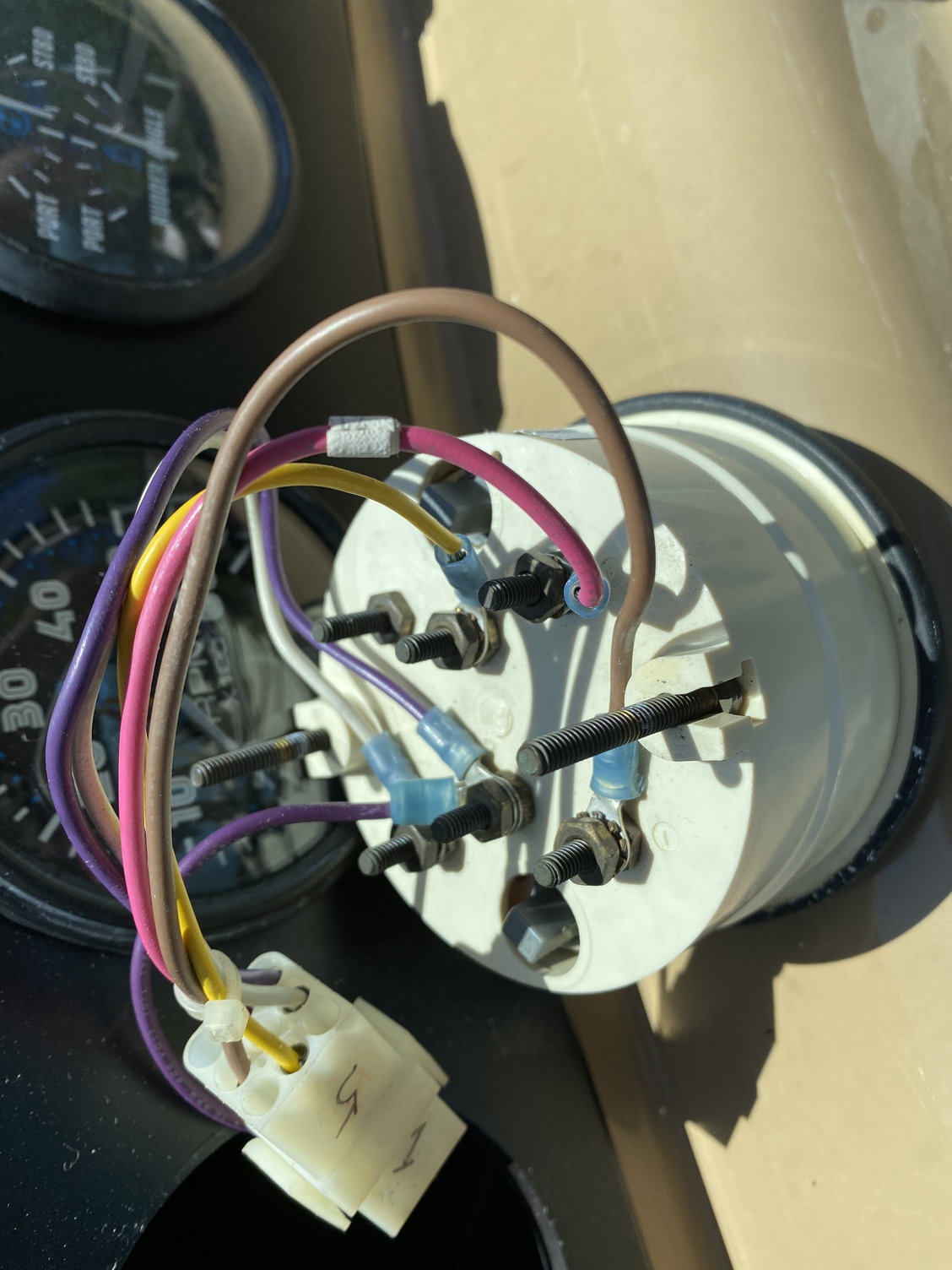
Unravelling someone else's "creative" gauge wiring. Page 1 iboats
Whether you are upgrading your existing panel or starting from scratch, this comprehensive wiring diagram guide will provide you with 10 essential tips to help you complete the task successfully. One of the first things to consider when wiring your boat instrument panel is to carefully plan the layout.

Understanding Wiring Diagrams For Boat Fuel Gauges Wiring Diagram
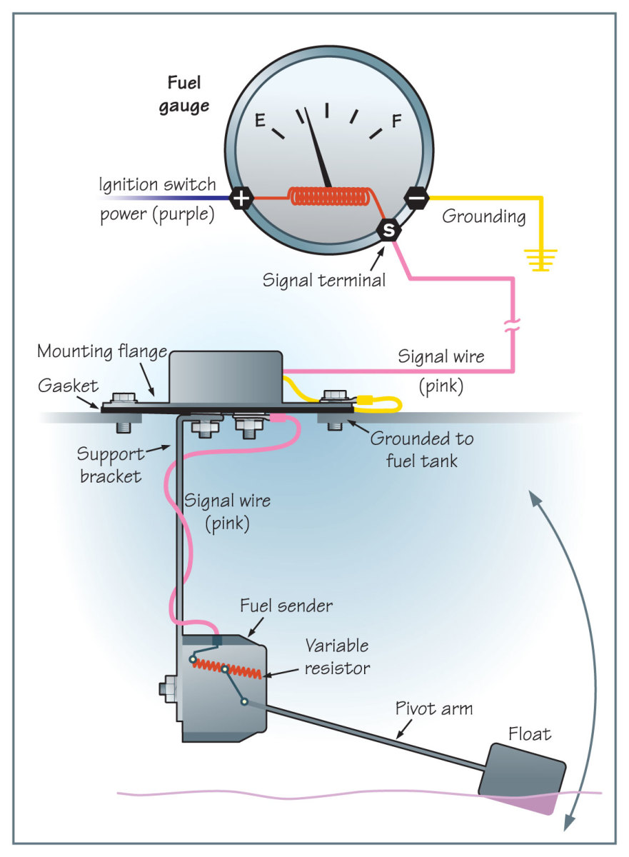
Fuel Gauge. The fuel gauge is the device that displays the amount of fuel in the tank. The gauge is connected to the power and ground wires, as well as the fuel sender unit. When the fuel sender unit detects a change in the level of fuel, it sends a signal to the fuel gauge, which then displays the updated level of fuel on its digital display.
OMC Gauge wiring color codes The Hull Truth Boating and Fishing Forum
A Teleflex marine gauge wiring diagram provides an easy-to-follow schematic for connecting the gauges to the engine and battery. By following the diagram, you can ensure that all the gauges are wired correctly, providing accurate readings. Additionally, the wiring diagram helps to identify any potential shorts or faults in the wiring system.
Wiring boat gauges diagram Aiiz
Load requirement and distance from the battery will help determine proper gauge wire and fuse requirements. For example, a trolling motor on a 20-foot boat should have 4 or 6 gauge wire for best battery utilization. Every problem cannot be solved with this checklist, but it will give you a good starting place.
Autometer Gauge Wiring Diagram Cadician's Blog
Here is how to wire a fuel gauge: 1. The first step is to disconnect the battery. This is to prevent any accidental shorts while you are working on the wiring. 2. Next, locate the sending unit. This is usually located in the fuel tank, but may be in the engine bay if your car has an external pump. 3.

Which gauges will work as replacements? The Hull Truth Boating and
than 18 gauge, that is approved for marine use. It is recommended that insulated wire terminals, preferably ring type, be used on all connections to the gauge and the sender, except the light which requires a 1/4" female blade terminal. 3. Cut a 2-1/16" diameter hole in the dash and mount the gauge with the backclamp supplied. 4.
mercontrol wiring diagram, Style Guru Fashion, Glitz, Glamour, Style
Shop Pontoon Stuff for your all of your pontoon restoration needs, like the console shown in the video. Please use our link when you shop:www.pontoonstuff.co.
