Proform Electric Water Pump Wiring Diagram
Wiring Diagram For Water Pump Wiring Diagram Schemas
This video explains the operation of a reciprocating hand pump with relevant animation. Hand pump is a manually operated water pumping device that uses no el.

Sensational Qb60 Water Pump Wiring Diagram 2 Gang
1 Fit a PVC pipe into 1 of the branches of a PVC tee socket. Take a 10 in (25 cm) long, 1 inch (2.5 cm) diameter PVC pipe and slide it into 1 of the branch openings of a 1 inch (2.5 cm) diameter PVC tee socket, leaving the other end open.

shurflo water pump wiring diagram
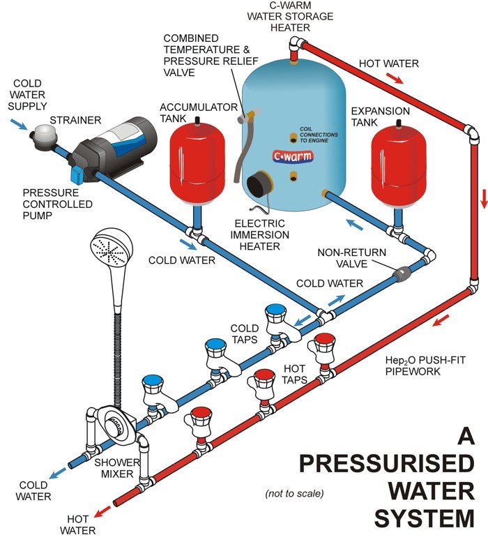
Diagrams --Typical Pump Installations. The information provided here is for educational purposes only. Technically qualified personnel should install pumps and motors. We recommend that a licensed contractor install all new systems and replace existing pumps and motors. Failure to install in compliance with local and national codes and.
Rv Water Pump Flow Diagram Diagrams Resume Template Collections
Single phase pumps are used in most residential applications. A single phase motor has two wires: a black "hot" wire and a white "neutral" wire. Once the type of pump has been determined, the next step is to identify the wires associated with the pump. The wires should be labeled on the pump itself. If not, look for a label on the motor housing.
[DIAGRAM] Wiring A Water Pump Diagram
Jet pumps are mounted above the well, either in the home or in a well house, and draw the water up from the well through suction (see Single-Drop Jet-Pump System diagram on next page)..

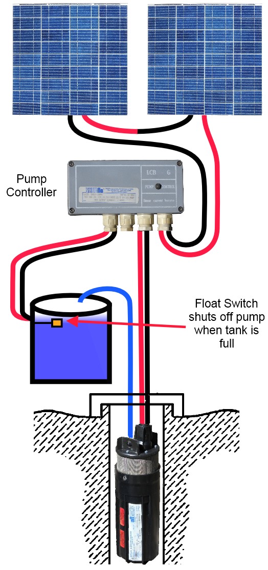
Schematic diagram of solar water pumping system. Download Scientific
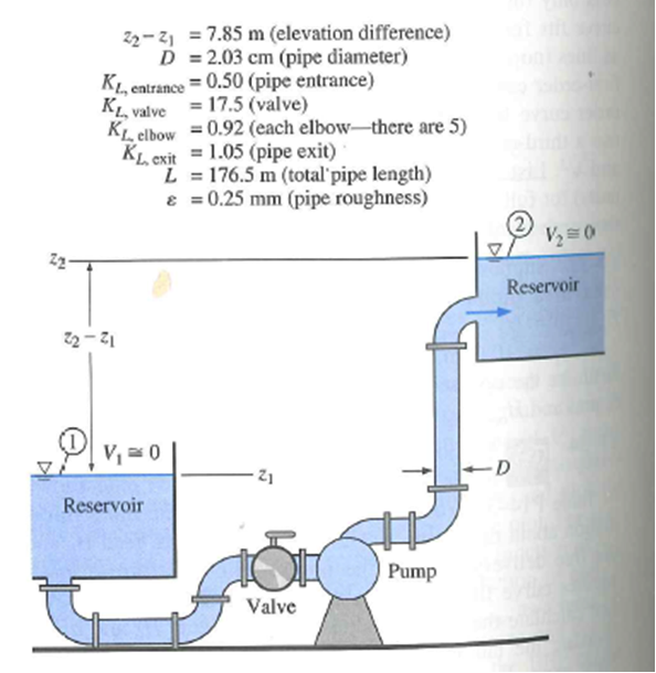
fittings to remove gases trapped in the pump casing or to drain the pump casing for maintenance. Figure 1 is a simplified diagram of a typical centrifugal pump that shows the relative locations of the pump suction, impeller, volute, and discharge. The pump casing guides the liquid from the suction connection to the center, or eye, of the impeller.

4S4Z8501E Ford Engine Water Pump. PUMP ASSEMBLY WATER. Water pump
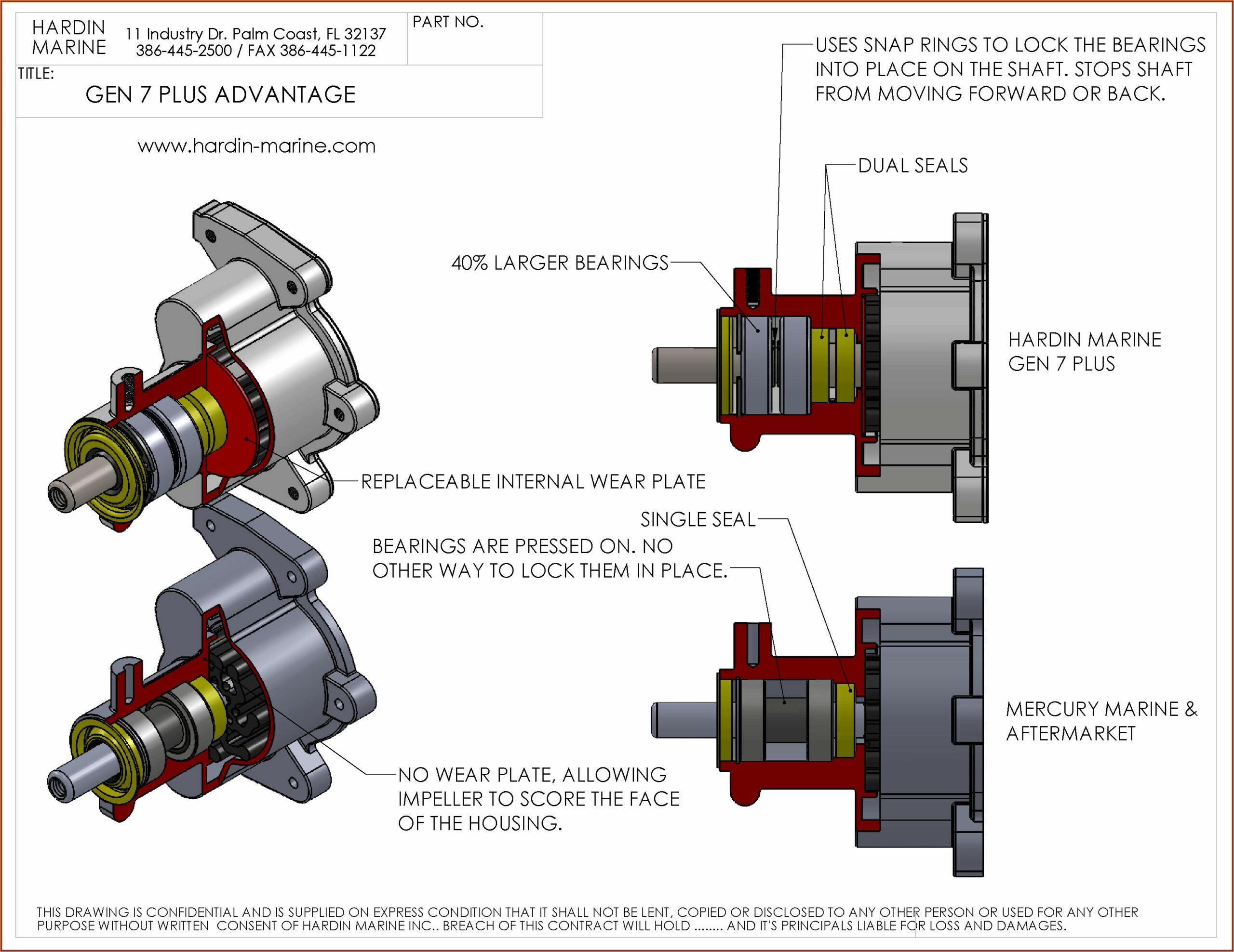
A water pump schematic diagram is an abstract drawing of a pump's internals and shows how each component works together to move water from one source to another. The diagram includes the motor, impeller, impeller shafts, bearing supports, housing, and installation components.

12681165 General Motors Engine Water Pump Housing GM Parts Depot
This video explains how to wire a water motor in a house, how to connect a capacitor and how to test motor winding ohms.Wiring a single-phase water pump typi.

EJ7Z8501F Ford Water. Pump. Engine. Assembly Lakeland Ford Online
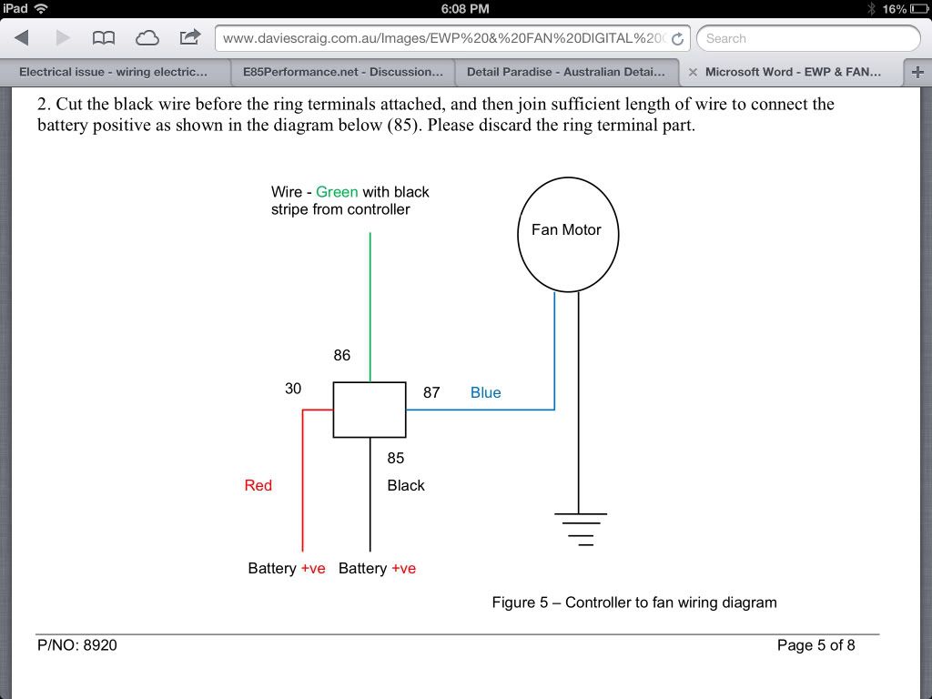
An electrical diagram of a water pump provides a visual representation of the various components and connections involved in its electrical system. It typically includes a power supply, motor, control panel, capacitors, relays, and other electrical accessories.
Shurflo Water Pump Wiring Diagram General Wiring Diagram
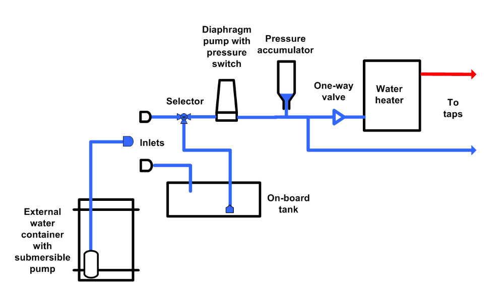
A diaphragm pump (also known as a Membrane pump) is a positive displacement pump that uses a combination of the reciprocating action of a rubber, thermoplastic or teflon diaphragm and suitable valves on either side of the diaphragm ( check valve, butterfly valves, flap valves, or any other form of shut-off valves) to pump a fluid . Those in.
Proform Electric Water Pump Wiring Diagram
Two-Wire Well Pump Wiring Diagrams 2-wire well pump diagrams are slightly easier to understand, and are more straight-forward to wire. Black wires go to black wires, and the green wire (the ground) goes to the ground wire. Fig. 1 (Above): 2 Wire Well Pump Wiring Diagram Three-Wire Well Pump Wiring Diagrams
[DIAGRAM] Wiring A Water Pump Diagram
This instructable shows how to build a fairly simple water pump that needs no energy input other than water flowing from a higher point to a lower point. Most of the pump is constructed from PVC, with a couple of bronze pieces thrown in for flavor. I was able to source all of the parts from a local hardware store (Lowes) for a bit under $100.

2015 Ford F250 Super Duty Engine Water Pump. PUMP ASSEMBLY WATER
The centrifugal pump defines as a hydraulic machine that converts mechanical energy into hydraulic energy by means of a centrifugal force acting on the fluid. In this, the pump uses a centrifugal force acting on the fluid surface to convert the mechanical energy. The centrifugal pump flows in a radially outward direction.
Wiring Diagram Water Pump Pressure Switch 35 Water Pump Pressure Switch
Water Pump The water pump is a simple centrifugal pump driven by a belt connected to the crankshaft of the engine. The pump circulates fluid whenever the engine is running. The water pump uses centrifugal force to send fluid to the outside while it spins, causing fluid to be drawn from the center continuously.

1610009201 Toyota Pump assembly, engine water. Pump, water. Pump
Understanding how electrical wiring diagrams work is the key to properly installing and running your water pump safely and effectively. Firstly, the diagram will show which wire color corresponds to which electrical component; this helps you avoid accidental connections or mistakes. Secondly, the wiring diagram will also outline the physical.

Shurflo Water Pump Wiring Diagram Solar Shurflo Wholefoodsonabudget
1 What You Will Need to Install a Well Pump Before you can install a shallow well pump, deep well pump or replace an existing unit, you'll need to ensure that you've got the right tools for the job.
