The basics of electrical control panel design Your Business Magazine
Electrical Panel Wiring Diagram
Figure 6.3 - Industrial Control Panel Schematics Using EPLAN | EPLAN Control Circuit Page Neutral. Note, the number "2.7" indicates that the "Interruption point" is connected to N, corresponding to page 2, row 7 in the schematic. Note, it would be beneficial to create a separate page for Power Supply Wiring, enhancing the organization and clarity of the schematic.

How To Read Electrical Diagrams Wiring Explained Control Panel Diagram Wiring Digital and
Control Panel Design Considering Electrical Safety Standards Points on Panel Design for Conformance to IEC 60204-1 P.20. connector lists, etc.) can be edited from any diagram and the changes will be reflected in all the related diagrams and lists in real time.
Free download Electrical control panel wiring CAD drawing Cadbull
The first step in reading control panel wiring diagrams is to get familiar with the layout. Each diagram is going to be unique, but many of them will follow the same general format. Look for the power source, circuit breakers, and other components that are labeled on the diagram. This will give you a good starting point for understanding the.

Electrical Wiring Diagram Symbols Pdf / Electrical Control Panel Wiring Diagram Pdf Free
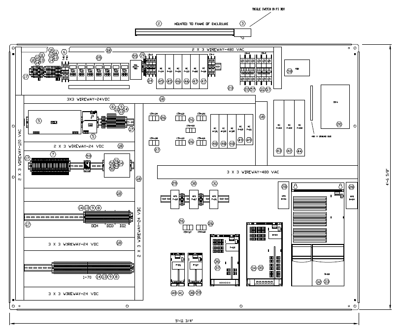
1 • start physical Good control panel design includes physical and electrical requirements. Don't shortcut the design process and produce schematic drawings without producing physical layout drawings. Alternate between the physical and electrical until all potential problems have been solved.

Instrument Control Panel AutoCAD Free CAD Block Symbol And CAD Drawing
Other bodies have issued applicable standards as well, such as IEC 60204-1, which relates to the safety of machinery and electrical equipment of machines. Given the many standards applicable to specific types of industrial control panels and those intended for use in specific applications, it's imperative to identify the appropriate standards at the beginning of the design process.

the wiring diagram for an electronic device
Wiring diagrams provide an overview of the wiring and devices in a system. Being able to properly read diagrams allows industrial controls facilities to maintain, operate, and troubleshoot as needed. Much of the troubleshooting, repair, and construction of an electrical system begins at a technician's ability to read a wiring diagram.

Basic electrical design of a PLC panel (Wiring diagrams) EEP
Industrial Control Panels and Electrical Equipment of Industrial Machinery for North America A Guide for Practical Use . Reference Manual 08/2014 . A5E02118900A/RS-AA/002 . Disclaimer of Liability . 1 . 2. Introduction . Area of application for this . documentation . 3. General information for . manufacturers of machinery and their associated.

LT panel Design with AutoCAD Electrical AutoCAD Electrical control Panel drawing, Panel
A control system of a PLC panel will normally use AC and DC power at different voltage levels. Control cabinets are often supplied with single phase AC at 220/440/550V, or two phase AC at 220/440V AC, or three phase AC at 330/550V.

The basics of electrical control panel design Your Business Magazine
With Control Panel Design in the TIA Selection Tool, electrical engineering is completely digital and integrated. You can design the main and control current components and the power supplies with just a few clicks and obtain a correct short-circuit calculation and cable dimensioning. You can then print out the results as documentation. Use.
Fully Programmed and Customized Process Control Systems Koch Modular
Here are basic steps for creating control panel designs. Chris Kregoski, product engineer for AutomationDirect, wrote an article posted in April 2022 on PanelBuilderUS.com titled Designing and Assembling Control Panels. Here's a summary, click on the link above for the full text.

The basics of electrical control panel design Your Business Magazine
The National Electrical Code (NEC) is a standard for the design and safe installation of electrical equipment in the United States. NEC and related regulations dictate many features of ICPs. Figure 1. An ICP that follows industry standards and best practices. Image used courtesy of UL Solutions

How to read electrical panel drawing drawing panel drawing in hindi YouTube
Discovering Control Panel Diagrams: A Comprehensive GuideCreating electrical control panels can be a complex task, but having the right diagrams can make the job simpler. Control panel diagrams are representations of how the components in the electrical system should be connected and how they operate. This guide will explain the fundamentals of control panel diagrams and the importance.
AutoCAD Electrical Control Panel Board Drawing Tutorial for Electrical Engineers YouTube
They are a type of technical drawing that provides a visual representation describing electrical systems, circuits and other electrical components. After they are completed, electrical designs and drawings are used to explain the design to Electricians or other workers who use them as a map to successful installation or repairing processes.
Electrical Control Panel Installation Drawing
Electrical equipment 6 Devices in the control panel and the machine environment 7 Use of IE2 and IE3 motors 8 Engineering support with data and tools A. Control Panels compliant with IEC Standards and European Directives 8 Reference Manual, 10/2017, A5E38284819002A/RS-AB/002

ικανότητα υποστήριξη παρέμβαση electrical panel board drawing Τζέμπεθ Γουίλσον μουστάρδα Διαφανής
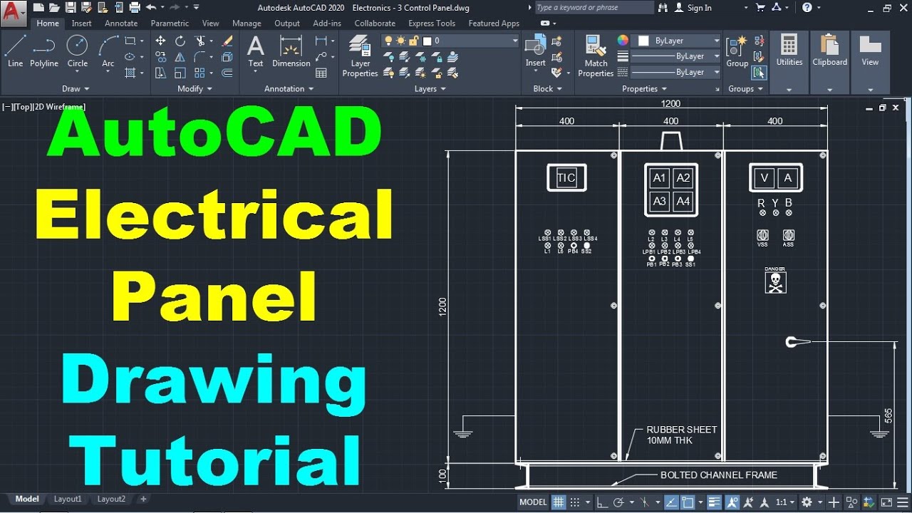
This tutorial shows how to create electrical panel board drawing in AutoCAD step by step from scratch. Learn AutoCAD electrical control panel design, AutoCAD electrical panel.

diagram wiringdiagram diagramming Diagramm visuals visualisation graphical Check more at
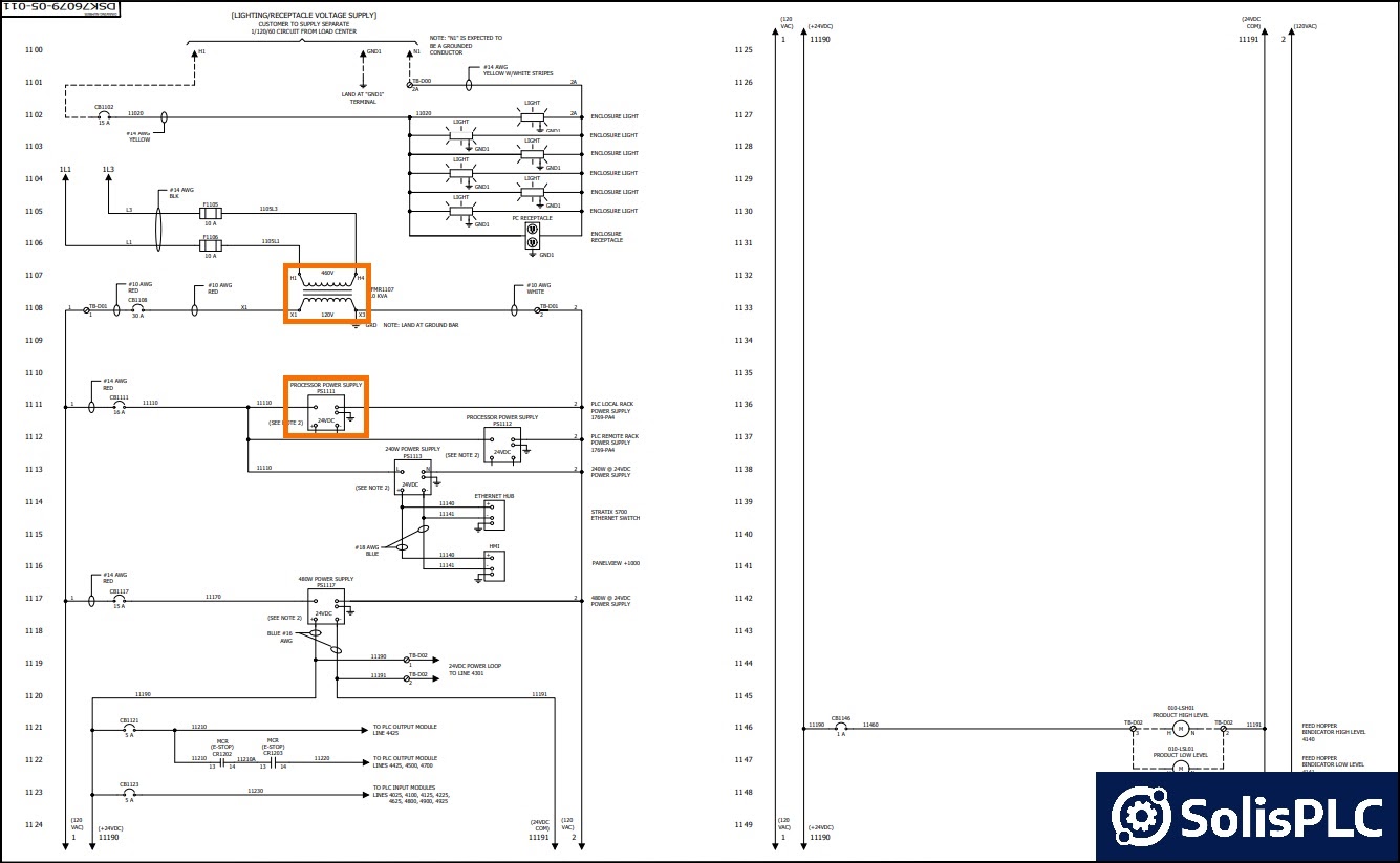
Electrical panel wiring diagrams are used to outline each device, as well as the connection between the devices found within an electrical panel. As electrical panels are what will contain control systems, panel wiring diagrams are commonly encountered by PLC technicians and engineers.
