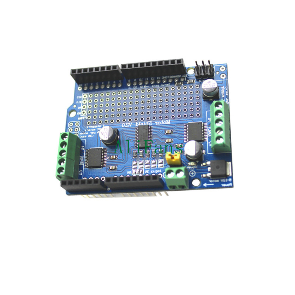
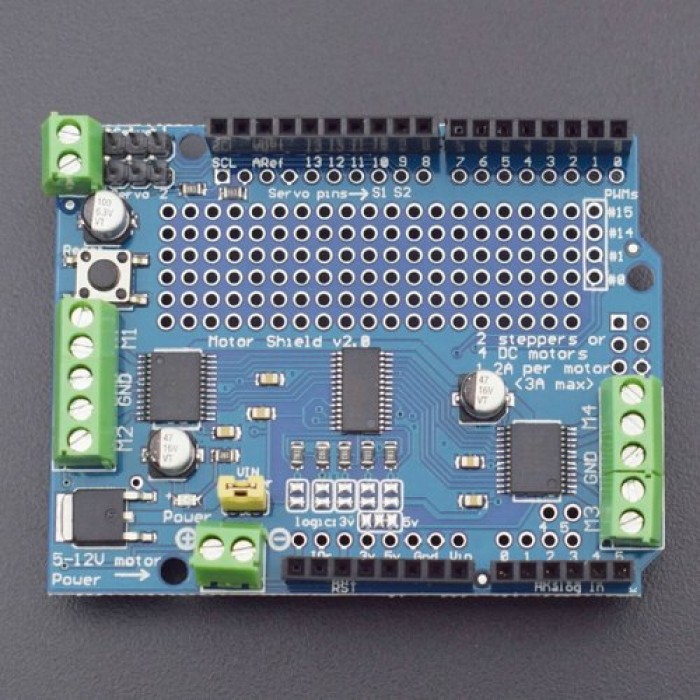
I2C TB6612 Stepper Motor PCA9685 Servo Driver Sheld V2 Für Arduino Robot PWM eBay

I2C stepper motor driver EasyEDA open source hardware lab
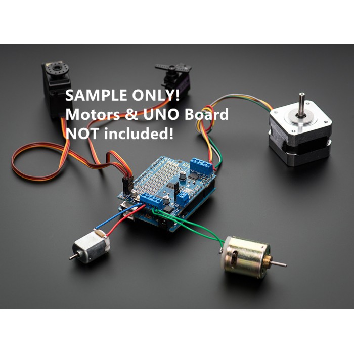
Description Using the QWIIC enabled I2C-IO and L298N motor controller, stacked together with a muffin fan for cooling, you can assemble an I2C bus controlled stepper motor. The device appears on the I2C bus as a stack of registers to control motor power, step direction, number of steps to take and status (busy/not busy).

Grove I2C Motor Driver (L298P) (Seeed Studio) SS105020093 Core Electronics Australia
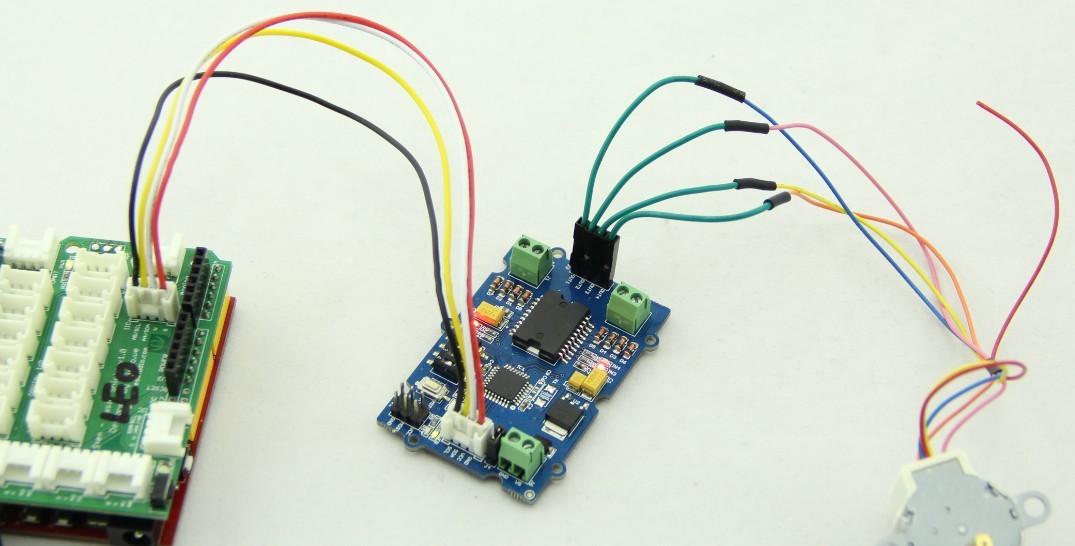
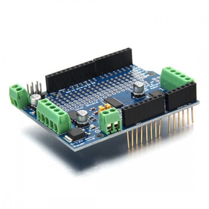
The Grove - I2C Motor Driver V1.3 (latest version) can directly control Stepper Motor or DC Motor. Its heart is a dual channel H-bridge driver chip(L298P)that can handle current up to 2A per channel, controlled by an Atmel ATmega8L which handles the I2C communication with for example an Arduino. Both motors can be driven simultaneously.
Grove I2C Motor Driver V1.3
Features MCU: STM32f030f4P6 microcontroller for burning the code and control the Motor Driver. L298P Motor driver chip: common use for a motor driver and can drive stepping motor and servo motor. Selectable I2C address: change the connection of wire hat to get the I2C address from 0x00 to 0x0f, the default I2C address is 0x0f.
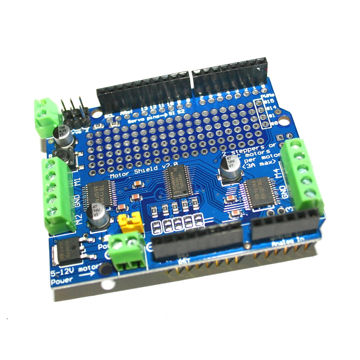
IIC I2C TB6612 Mosfet Stepper Motor PCA9685 PWM Servo Driver Shield V2 For Arduino Robot PWM Uno
Driving stepper motors using NXP I2C-bus GPIO expanders Rev. 2 — 11 October 2011 Application note Info Content Keywords stepper, stepper motor, GPIO, push-pull, quasi-bidirectional, MOSFET, optical interrupter, Fast-mode Plus, Fm+, I2C-bus Abstract The NXP GPIOs offer an alternative to expensive application specific stepper motor driver ICs.
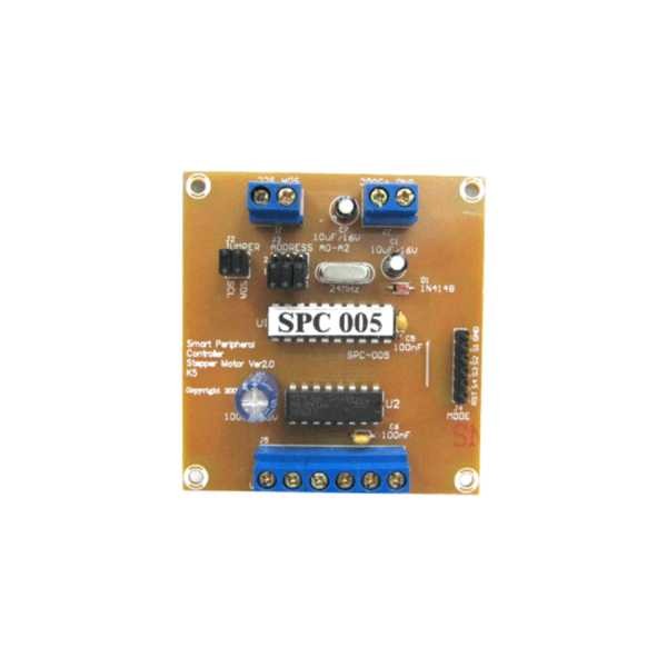
Stepper Motor Driver I2C Paralel Smart SPC Digiware Store
The Grove - I2C Motor Driver (TB6612FNG) can drive two DC motors up to 12V/1.2A or one stepper motor up to 12V/1.2A. With the on-board MCU, it easily works with Arduino via the Grove I2C interface. This diver board is based on TB6612FNG, which is a driver IC for DC motor and stepper motor with output transistor in LD M
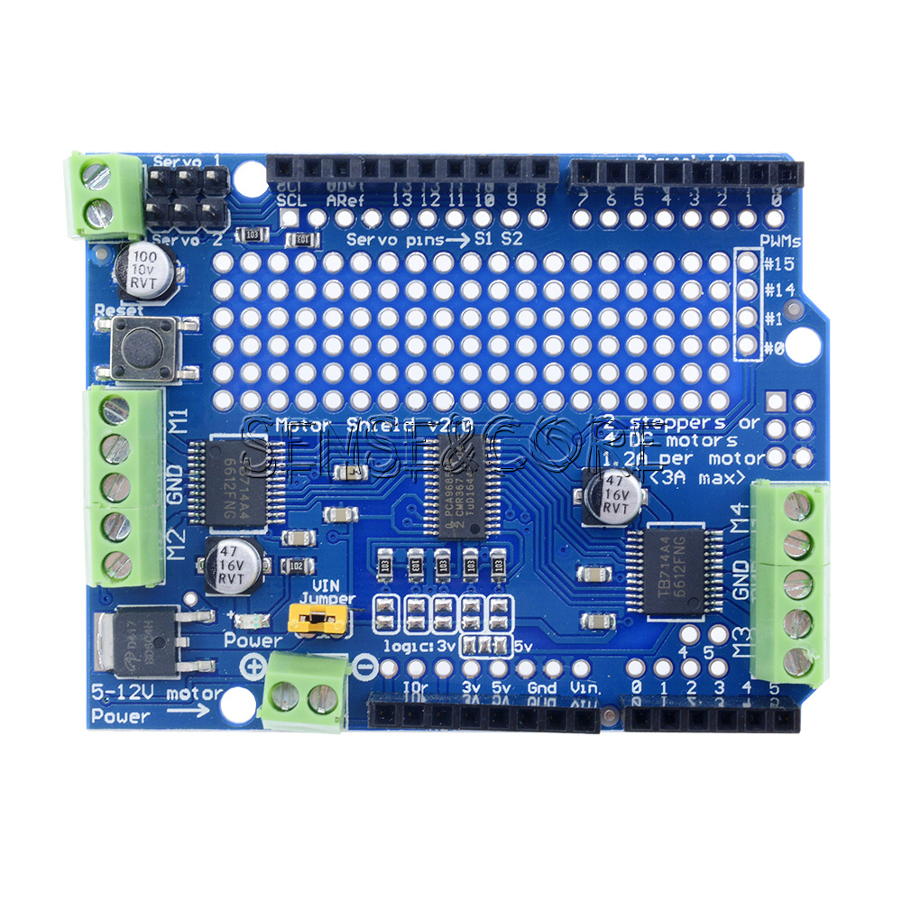
I2C TB6612 Stepper Motor PCA9685 Servo Driver Sheld V2 Für Arduino Robot PWM eBay
The Stepper Driver Arduino is designated as I2C Master and the IR Remote Handler is designated as I2C slave. The Stepper Driver Arduino uses an interrupt service routine (ISR) to command each step. The main loop polls for I2C data from the IR Remote Handler and sets flags used by the ISR to control the steppers. Using an ISR, as opposed to.

Stepper motor control with I2CLCD display Project Guidance Arduino Forum
Stepper motor control Hardware Overview Pin Out Hardware Detail I2C Interface This board uses the I2C interface to allow the on-board MCU to communicate with the host computer. GND: connect this module to the system GND VCC: you can use 5V or 3.3V for this module SDA: I2C serial data SCL: I2C serial clock Power In
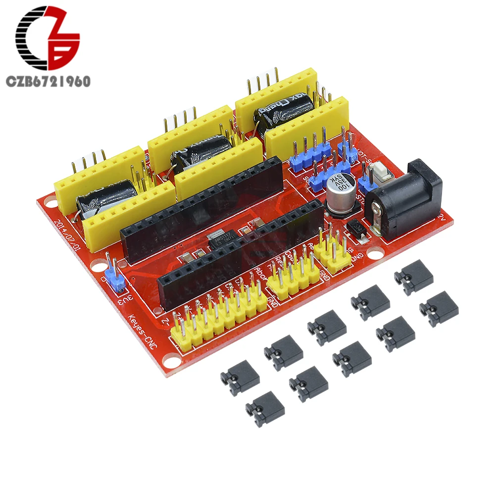
I2C IIC CNC Shield V4 Engraving Machine 3 Axis Stepper Motor Driver Expansion Board 3 Channel
TI's DRV8830 is a 7-V, 1-A H-bridge motor driver with speed regulation and I2C control. Find parameters, ordering and quality information
Arduino DC Motor / Stepper / Servo TB6612FNG 1A 3A MAX Motor Driver i2c iic Expansion Shield V2
Model: ROB72212P Features Grove Compatible I2C Interface Adjustable motor speed and rotation direction Changeable slave address by hardware Specifications Interface Function 78M05 IC: 5v voltage regulator L298 IC: dual full bridge driver Atmega8 IC: Control Motor Rotate.

Stepper Motors I2C TB6612 Stepper Motor PCA9685 Servo Driver Sheld V2 For Arduino Robot PWM New
Features On board MCU CW/CCW/short brake/stop function modes Built-in thermal shutdown circuit and low voltage detecting circuit Standby (Power save) system Specification Typical applications DC motor control Stepper motor control Hardware Overview Pin Out Hardware Detail I2C Interface
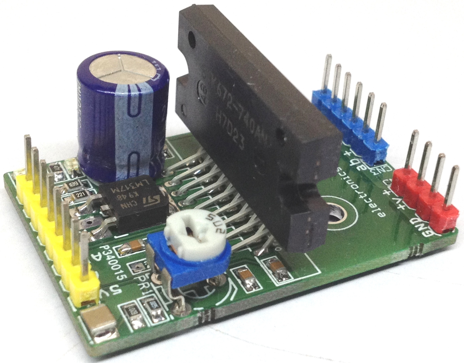
4A PWM Controlled Unipolar Stepper Motor Driver using STK672740
This is the Arduino library of Grove - Motor Driver(TB6612FNG), based on I2C. Examples dc_motor. This example shows how to drive a dc motor. Connect a dc motor to the same channel(A1 and A2, or B1 and B2) first.. stepper_motor_2phase. This example shows how to drive a 2phase stepper motor. Different with dc motor, there is just one function.
Arduino DC Motor / Stepper / Servo TB6612FNG 1A 3A MAX Motor Driver i2c iic Expansion Shield V2
The Grove - I2C Motor Driver V1.3 (latest version) can directly control Stepper Motor or DC Motor. Its heart is a dual channel H-bridge driver chip(L298N)that can handle current up to 2A per channel, controlled by an Atmel ATmega8L which handles the I2C communication with platforms such as Arduino.
I2C TB6612 Stepper Motor PCA9685 Servo Driver Board Sheld V2 F Arduino Robot PWM eBay
Step 2: Getting Started. The Grove I2C Motor Driver, has a dual channel H-Bridge (L298) which can handle 2A per channel. Controlled by an Atmel ATmega8L which handles the I2C communication. I2C is a is 2 pin communication system the 2 lines are the SDA (data line) and SCL (clock line), this reduces the number of pins of the Arduino dedicated to.
Arduino DC Motor / Stepper / Servo TB6612FNG 1A 3A MAX Motor Driver i2c iic Expansion Shield V2
The PCA9629A is an I²C-bus controlled low-power CMOS device that provides all the logic and control required to drive a four phase stepper motor. PCA9629A is intended to be used with external high current drivers to drive the motor coils. The PCA9629A supports three stepper motor drive formats: one-phase (wave drive), two-phase, and half-step.

I2C Motor Driver Atmel ATmega8L Dual Channel HBridge Driver Power Brushed DC Motors and 1
Design and Implementation of Stepper Motor Control Over I2C 1 Application Report SLVAE40-November 2018 Design and Implementation of Stepper Motor Control Over I2C Communication Vashist Bist, Analog Motor Drives Manu Balakrishnan, Industrial Systems ABSTRACT

Arduino + LCD+I2C + Stepper+EasyDriver, YouTube
It is ready to build intelligent peripheral systems where up to 32 drivers can be connected to one I 2 C master. This significantly reduces system complexity. The device receives positioning instructions through the bus and subsequently drives the stator coils so the two-phase stepper motor moves to the desired position.
