Wiring Diagram Goodman Air Conditioners

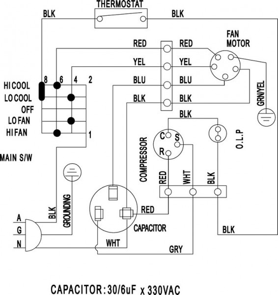
Typical Air Conditioner Wiring Diagram
Intro How to Read Wiring Diagrams for HVAC Equipment MEP Academy 21.5K subscribers Subscribe Subscribed 16K views 11 months ago Electrical and Power Learn how to read HVAC Electrical Wiring.

Wiring Diagram Goodman Air Conditioners
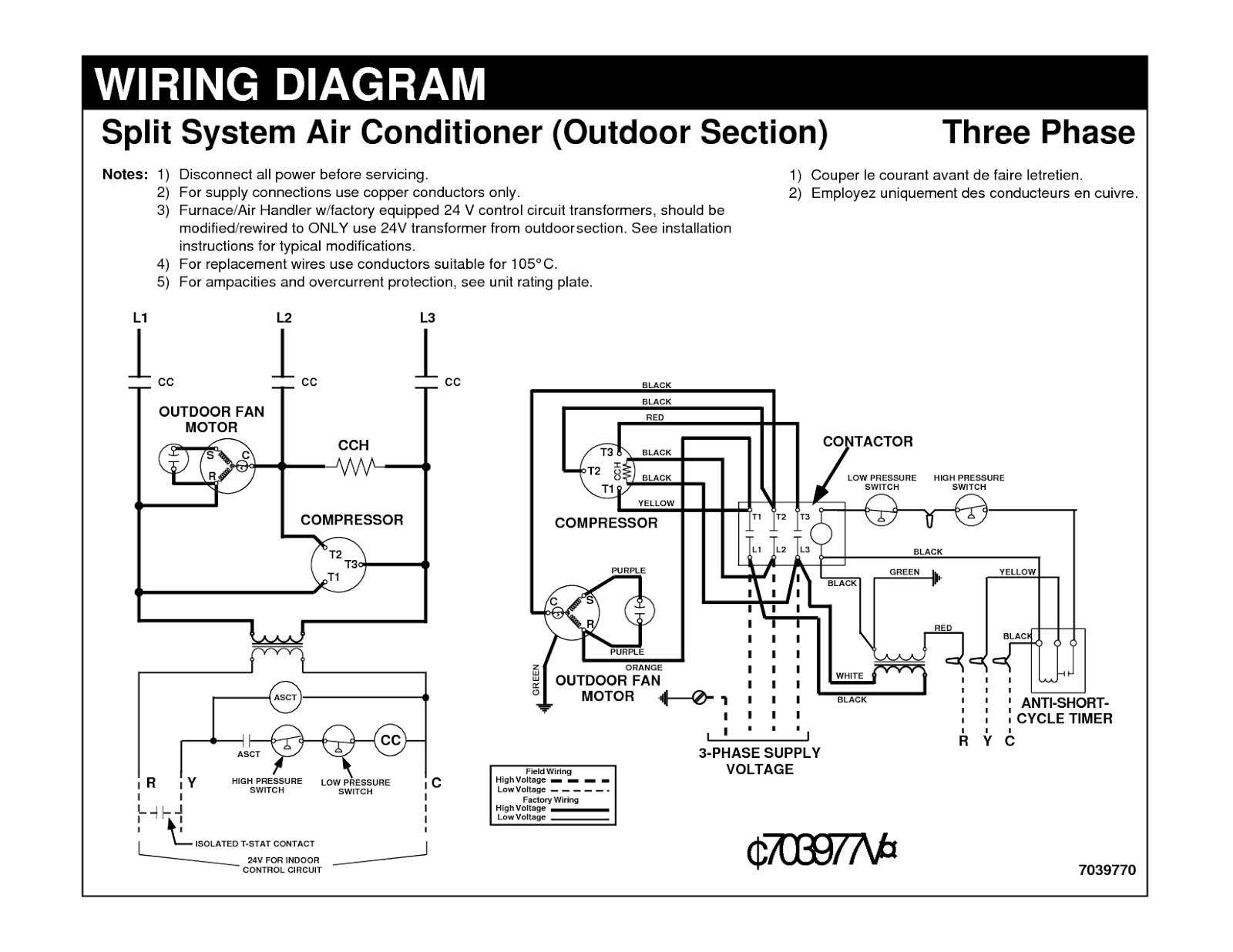
Baset Series Air Conditioner with Puron r 1---1/2 to 5 Nominal Tons Single and Three Phase Wiring Diagrams NOTES: 1. Symbols are electrical representation only. 2. Compressor and fan motor furnished with inherent thermal protection. 3. To be wired in accordance with National Electric N.E.C. and local codes. 4.

Goodman Air Conditioners Wiring Diagram Free Wiring Diagram
WIRING DIAGRAM MANUAL Split System Horizontal Air Conditioner 421 03 1600 00 3 Specifications subject to change without notice. 345082−101 — (C,H,T)SA660GKB 345082-101 REV. A 1. Compressor and fan motor furnished with inherent thermal protection. 2. To be wired in accordance with National Electric Code (N.E.C.) and local codes. 3.
Air Conditioner Wiring Diagram Pdf Window Ac Csr Carrier Split Car
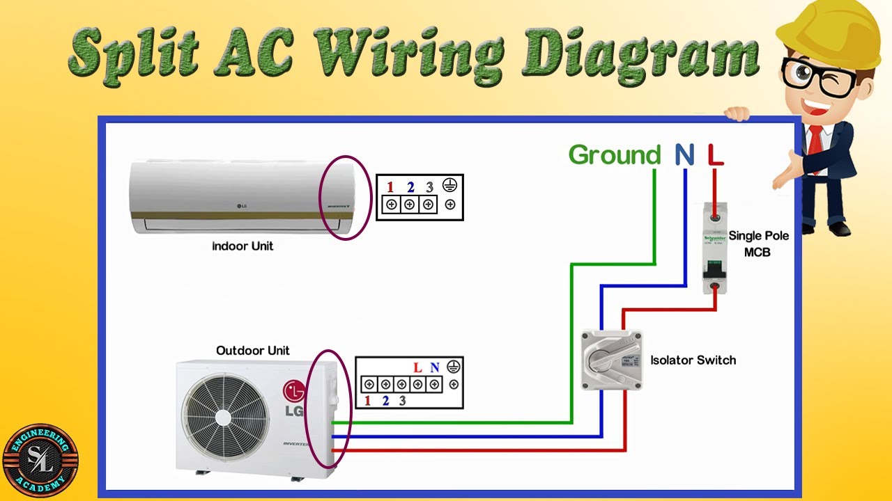
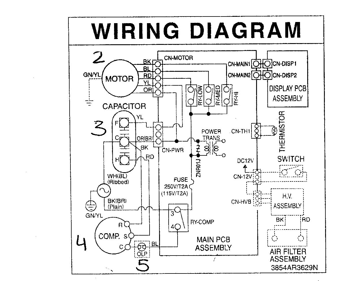
Locate the air conditioner's terminal block: The terminal block is where the electrical connections are made on the air conditioner unit. It is typically located on the side or back of the unit. Refer to the air conditioner's user manual or wiring diagram for guidance on locating the terminal block.
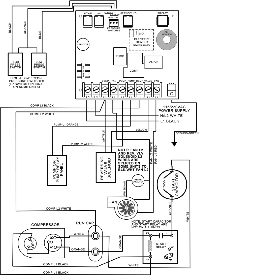
Duo therm rv air conditioner wiring diagram
How to read Electrical Wiring Diagrams? Today, I will explain Electrical Wiring for different Air-Conditioning Systems Types and Equipment. Third: Electrical Wiring Diagrams for Air-Conditioning Systems - Continued The Electrical wiring diagrams for Typical Air conditioning equipment

Air Conditioner Wiring Diagram
Is My HVAC System a 24-volt System? 3 Method to Wire a Thermostat. #1 Replace the thermostat wire for wire: #2 Locate the wiring connections in the furnace or air handler: #3 Use standard wiring colors to connect the thermostat: Common Thermostat Wiring Options - 2 Wire to 8 Wire Thermostats. 2 Wire Thermostat Wiring.
Mini Split Ac Wiring Diagram
Mechanical Diagrams Alpine Standard AC with Standard Furnace Control Wiring 1st Stage Heat (White) 24 Volt+ Fan Only Operation Common Air Conditioning Standard Thermostat Some AC Systems will have a blue wire with a pink stripe in place of the yellow or Y wire. Standard AC with Two Stage Furnace Control Wiring 24 Volt+ Fan Only Operation Common
Electrical Wiring Diagrams for Air Conditioning Systems Part Two
Key Takeaways Depending upon how complex your HVAC system is, the number of thermostat wiring can differ. You can have 2 Wire thermostat that that only control heating all the way to 8-wire and beyond that control, heating, cooling, fan, reversing valve, emergency heat, second stage or even third stage heating or cooling etc.
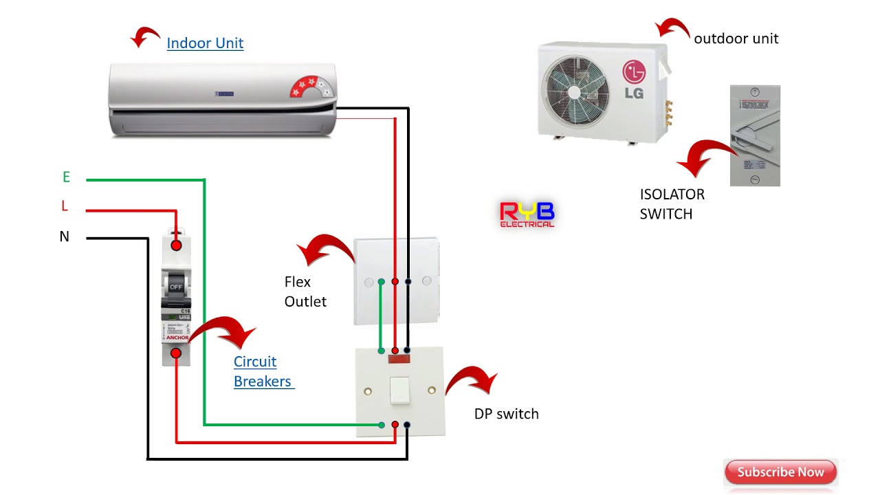
split system air conditioner wiring diagram
Wiring a central air conditioner involves setting up both high-voltage and low-voltage connections. First, turn off the power at the main electrical panel. Install a new 240-volt circuit breaker in your main electrical panel. Run electrical cable from the service panel to an air conditioner disconnect switch near the AC unit.
Electrical Wiring Diagrams for Air Conditioning Systems Part One
We walk through some of the basics and most common symbols associated with reading air conditioner wiring diagrams. Whenever you approach a wiring diagram, look at the whole thing, especially the legend and notes. In many cases, factory wiring will show up as solid lines and field wiring will show up as dashed lines.

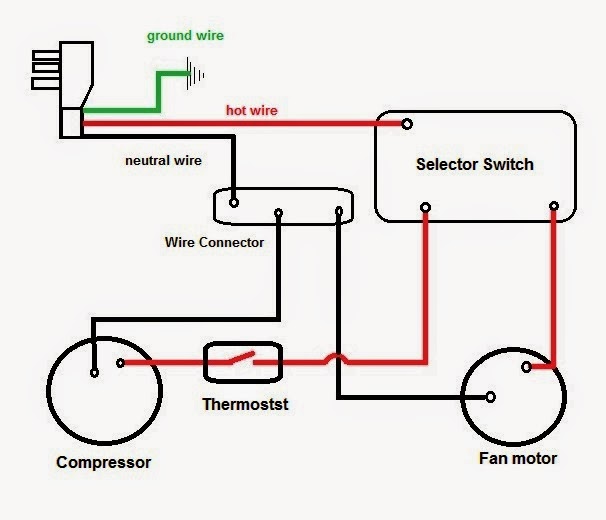
How to Wire an Air Conditioner for Control 5 Wires
Learning to Read Wiring Diagrams . We need to understand wiring diagrams and the main components and their differences. I remember pulling panels off HVAC systems, air conditioners, or a heat pump system as an apprentice, putting my finger on the power source, and following the diagram until I came across a component, usually a switch or a load.
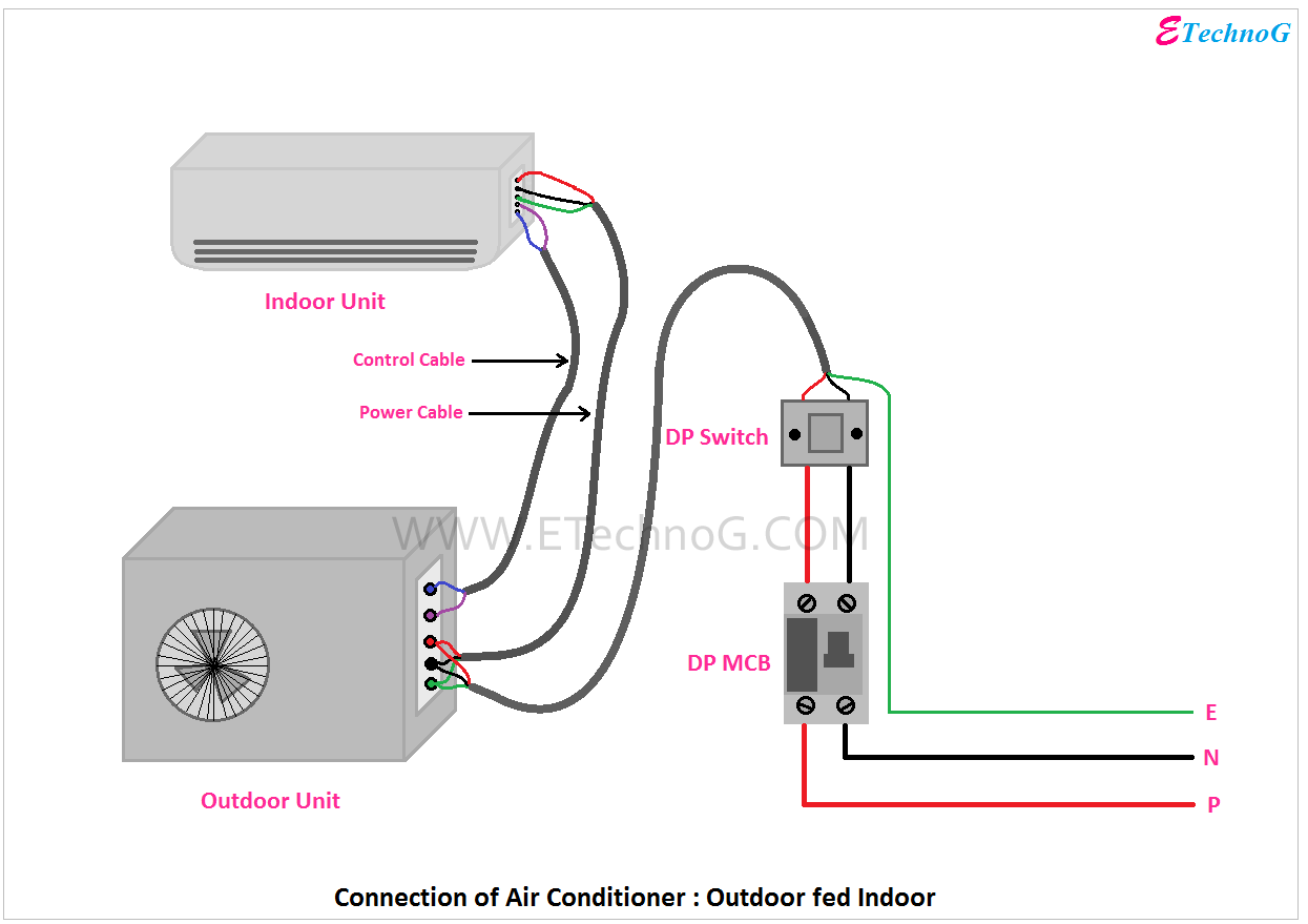
Air Conditioner Connection and Wiring Diagram ETechnoG
Wiring diagrams are used for the installation of the HVAC equipment, trouble shooting, or locating an electrical device in the control panel or within the unit. There are differences between the type of diagrams based on what they're used for. Schematic Wiring Diagram often called a Ladder Diagram and a Pictorial Diagram

Comfortmaker Air Conditioner Wiring Diagram
1 Thermostat Wiring Tips To install your unit, you'll need to connect the correct wires to the corresponding terminals on the back of your new thermostat. Here is the industry standard color code for thermostat wires used for most systems: The W wire is connected to your heating system.
Central Air Conditioner Wiring Diagram Download Wiring Diagram Sample
Color Code, How it Works, Diagram! AC Service Tech LLC 451K subscribers Subscribe 8.2K 964K views 4 years ago CAPE MAY COUNTY In this HVAC Installation Training Video, I show How to Wire the Low.

Electrical Wiring Diagrams for Air Conditioning Systems Part Two
What Skills Are Needed for Air Conditioner Wiring? You don't have to be an electrician to wire an air conditioning unit, but a good understanding of home wiring practices helps. All but the smallest window air conditioners operate at 240 volts.

Daikin Inverter Air Conditioner Wiring Diagram
G Terminal to the Green Wire Y Terminal to the Yellow Wire C Terminal to the Blue Wire Red Wire for Air Conditioner Control Power (Hot) | How to Wire an Air Conditioner for Control 1The R terminal is the 24-volt hot feed from the control step-down transformer. That will power the relay, contactor, or complete the circuit in the circuit board.
