My Solar Adventures DIY solar and arduino projects
The solar power mobile charger circuit is construct using a 6V/500mW solar panel, a PN junction diode 1N4007, a green LED, an SL100 transistor, and a 4.7V/400mW zener diode. The diode is connect towards the positive line of the solar panel to avoid reverse polarity.
Electrical Engineering Possible Electric Circuit For Solar Mobile Phone Charger Universal
Solar power mobile charger circuit January 3, 2016 Team Analog 10 Comments This circuit helps you to charge your mobile phone battery and also some rechargeable battery with solar energy, before trying this circuit take extra care in battery polarity and current rating, if anything goes wrong the battery might explode.
Solar charger Controller Circuit Diagram Electronic Circuits Diagram
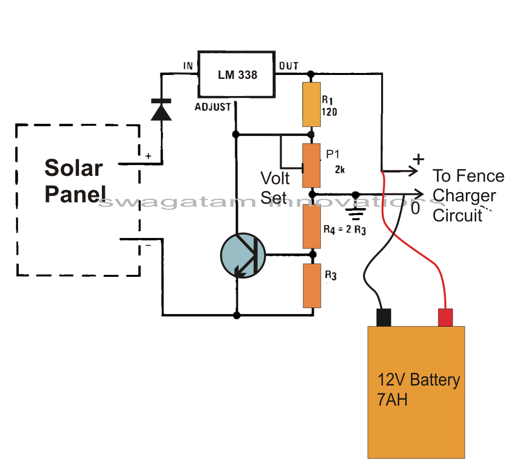
2k2 1/4 watt resistor - 1no That looks cool isn't it. In fact the IC and the diodes could already resting in your electronic junk box, so need of buying them. Now let's see how these can be configured for the final outcome. Estimated time taken to charge the battery from 11V to 14V is around 8 hours.
2 Amp Mobile Charger Circuit Diagram
2 Circuit Diagram. 3 Working Explanation. 4 Applications. A solar-powered mobile charger is a device that could charge cell phones with the help of solar radiation. A compact solar panel is the primary component of a solar mobile charger. The solar panel captures the energy coming from the sun and generates an output voltage.
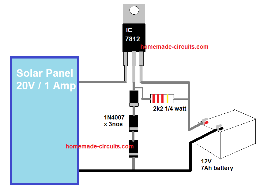
El tiempo estimado necesario para cargar la batería de 11 V a 14 V es de unas 8 horas.
The LT3652 is a multi-chemistry 2A battery charger designed for solar power applications. The LT3652 employs an input voltage regulation loop that reduces the charge current if the input voltage falls below a programmed level set by a simple voltage divider network.

Make this Solar Powered Fence Charger Circuit Homemade Circuit Projects
1 Comment This is the schematic diagram of solar powered mobile phone battery charger. The circuit is designed to charge the battery from a source with a lower voltage. Do not use it to charge the battery with the same or lower voltage than the voltage which is generated by the solar panel.

solar powered mobile charger circuit diagram, solar powered mobile charger circuit diagram
Step 1: Materials Required Solar panel 5.5V 245mA (3 Nos) 5V Boost converter module Switch Masking Tapes Wires Soldering kit Step 2: Working Explanation The Primary principle of this project is to convert solar energy into electrical energy.
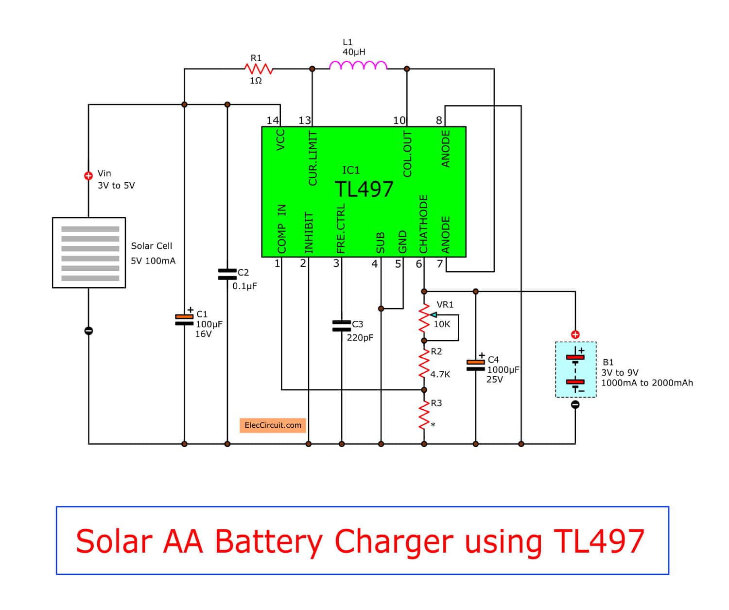
Make solar AA battery charger circuit by TL497 ElecCircuit
The solar panel is placed in direct sunlight - the more sunlight it receives, the faster it can charge your device. Now, let's break down the steps to constructing a circuit diagram for a solar-based mobile charger: 1. Start by connecting the positive and negative terminals of the solar panel to a blocking diode and then to the battery. 2.

scharf Ausbildung Süßigkeiten solar battery charger circuit Bund Üppig Abnutzen
By Clint Byrd|December 11, 2019 0 Comment A solar-powered mobile battery charger circuit is becoming an increasingly popular alternative to traditional charging methods. This innovative circuit uses the sun's energy to power your favorite device without needing a plug or electricity.

solar battery charging circuit diagram
Circuit Diagram for the Portable Solar Mobile Charger Source publication Design and Construction of a Portable Solar Mobile Charger Article Full-text available Apr 2020 Salim Mudi The state.
Diagram for Everything Solar Battery Charger Circuit Diagram Pdf
The circuit diagram for a solar mobile phone charger typically includes a solar cell, an integrated voltage regulator, a series of resistors, some capacitors, and a few other components. These components work together to deliver the correct output voltage, which is then transferred to the phone's battery and used to charge it.

Solar Mobile Charger and Powerbank Developpa
The circuit diagram of a solar battery charger is useful for anyone who wants to create their own mobile charger, or for those who want to repair or upgrade an existing device. Understanding the basics of a solar battery charger is key to making sure that your device works properly and lasts for a long time.

solar powered mobile charger circuit diagram, solar powered mobile charger circuit diagram
Shop for solar usb mobile charger circuit diagram at Best Buy. Find low everyday prices and buy online for delivery or in-store pick-up.. Larktale - Solar Charger - Black. Model: LK99403. SKU: 6472787. Rating 3.8 out of 5 stars with 20 reviews (20) Compare. Save. $39.99 Your price for this item is $39.99.
6V Solar Battery Charger Circuit Circuit Diagram Centre
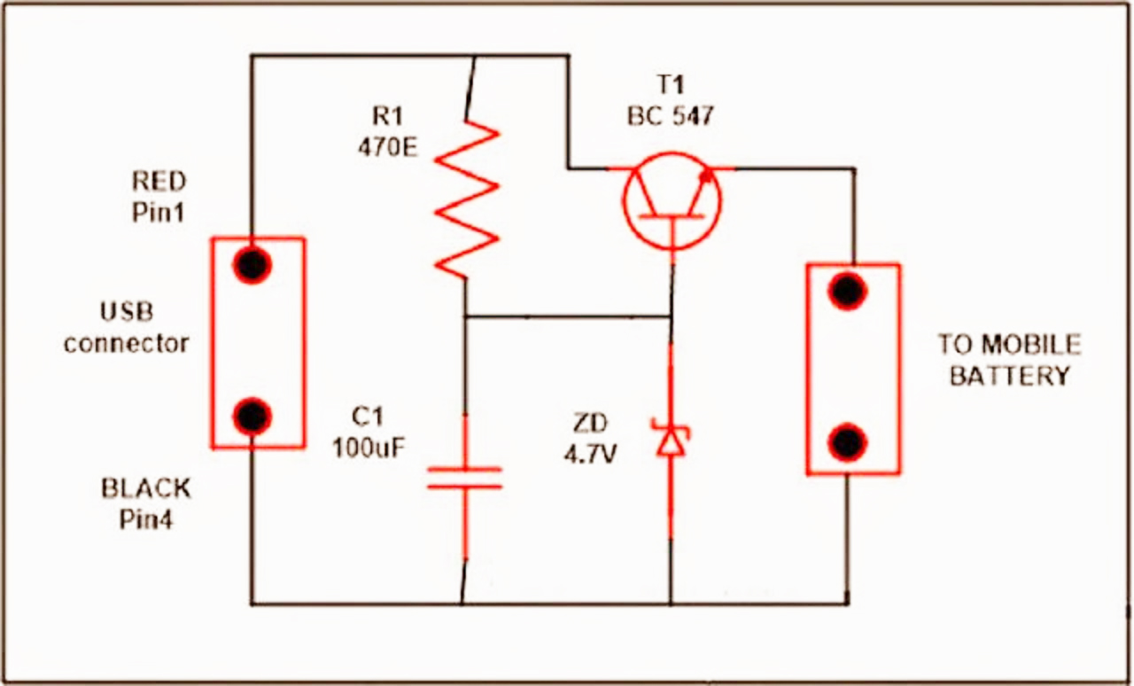
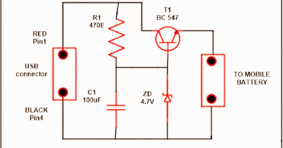
Circuit Diagram Working Explanation The Solar power mobile charger circuit uses a solar panel with a single PN junction diode 1N4007 connected to the solar panel's positive line to prevent reverse polarity. After the capacitor C1, a green LED is connected across the solar panel supply line to show the condition of the solar panel's supply output.
Mobile Charging Circuit Diagram
Specifications of the Charging Circuit Solar Battery Charger Circuit Diagram: Solar Battery Charger Circuit Design For Charging 12V Battery Output voltage Charging current Time taken for charging Power dissipation How to Operate this Solar Battery Charger Circuit? Solar Battery Charger Circuit Advantages: Solar Battery Charger Circuit Applications:
Circuit Diagram For Portable Mobile Charger
Circuit Diagram Circuit Construction and Working. In this circuit, we have utilized a 6V/500 mW solar panel, and then to avoid reverse polarity single PN junction diode 1N4007 connected towards the positive line of the solar panel. To provide the status of supply output from solar panel green LED connected across the solar panel supply line.
