Lucas 3 Wire Alternator Wiring Diagram For Your Needs
Repair Alternator
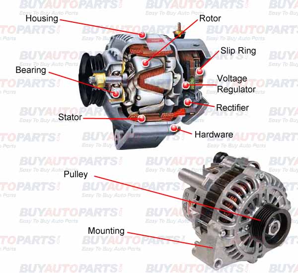
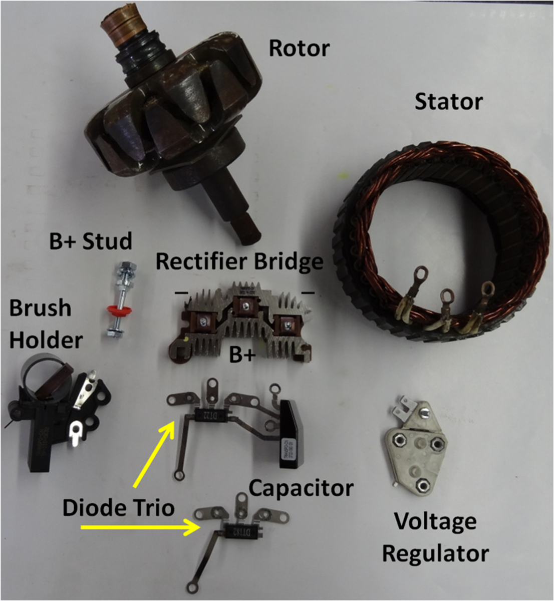
They include: Rotor assembly—field windings, claw poles, rotor shaft, and slip rings. Stator assembly—three stator windings, stator core, and output wires. Brush assembly—brush housing, brushes, brush springs, and brush wires. Rectifier assembly—diodes, heat sink or diode plate, and electric terminals.
Lucas 3 Wire Alternator Wiring Diagram For Your Needs
Alternator parts (stator, rotor, voltage regulator.) explained with fun, easy to understand demonstrations. Compare generator and alternator voltage output.

Alternator Connection Diagram Headcontrolsystem
The alternator has the following parts: Stator. Rotor. Exciter. Stator. It is a stationary portion consisting of stator frame and stampings etc. The stator frame is used for holding the armature stampings and the stator winding in position.. Alternator Construction - Explanation, Parts & Diagram. In this topic, you study Alternator or.
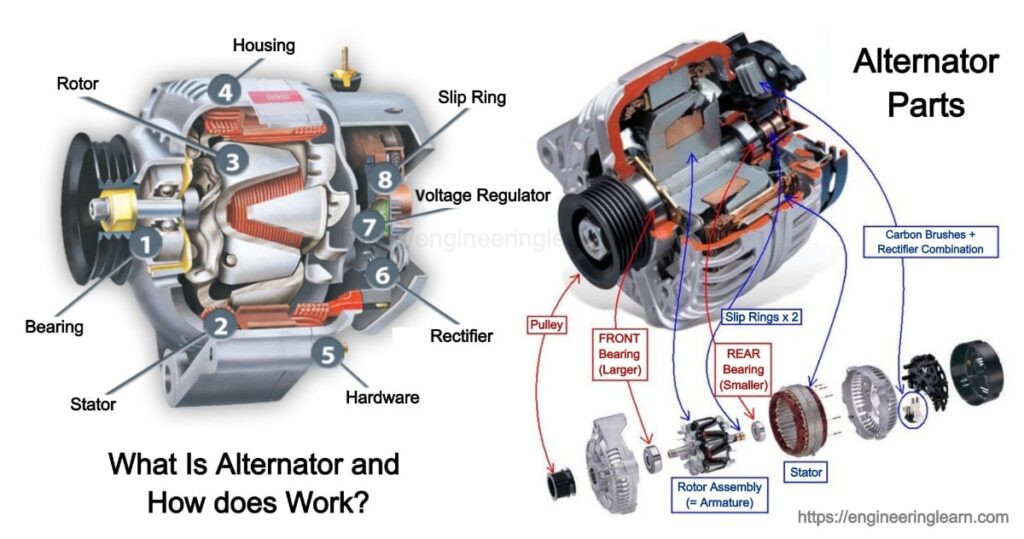
What Is Alternator and How does Works? Engineering Learner
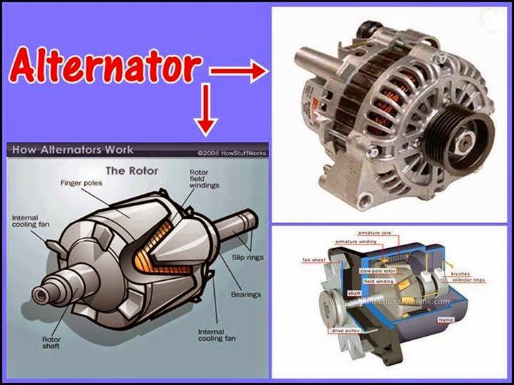
A basic alternator is made up of a series of alternating finger pole pieces placed around coil wires called field windings that wrap around an iron core on the rotor shaft. Since we know the pulley attaches to the shaft, we can now visualize how the rotor spins inside the stator.
Alternator Wiring Diagram B+ D+ W / Diagram 1984 Airstream Wiring Diagram Full Version Hd
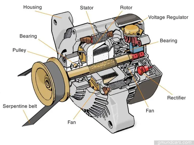
Alternators have three major components and they are the Rotor, stator, and rectifier. There are more components and we'll get to those as we progress through our discussion. 1. Alternator rotor Let's start with the rotor. A drive belt pulley system spins the rotor on a shaft while the vehicle engine is running.

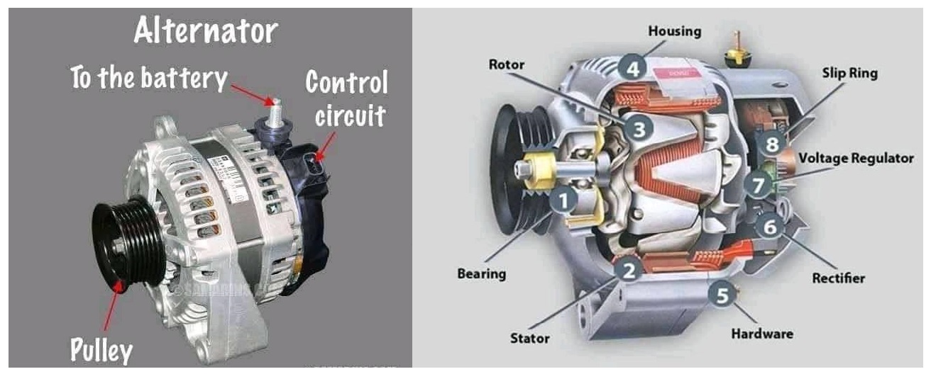
CIRCUITMIX on Instagram “Different parts of an alternator. What are the differences between an
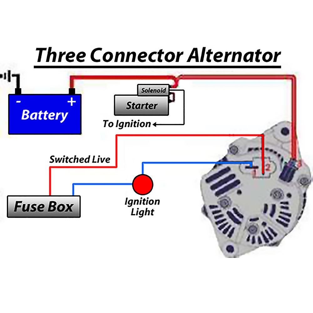
Figure 1, below, is a block diagram, or a "functional" diagram, of an alternator, and its connections to the remainder of the automobile electrical system. Following the figure is a description of the various components that make up an alternator, and a description of how each operates to keep the battery charged in your car. ALTERNATOR ROTOR
DIY Auto Service Alternator Diagnosis and Repair AxleAddict
Alternator Voltage Regulation 101 (with Wiring Diagrams) - In The Garage with CarParts.com Learn how a car alternator works and find detailed alternator wiring diagrams, including for 3-wire connections in this article. Read on.

Repair Guides Engine Electrical Alternator
The Charging System The charging system has three major components. The Battery, Alternator, and the Regulator. This alternator works together with the battery to supply power when the vehicle is running.

Can I Jumpstart A Car With A Bad Alternator What Does A Car Alternator Do One for the
(Fig. 1). Fig. 1: Portion of an alternator stator The magnetic core of the Stator is built-up of special steel stampings insulated from each other with paper, varnish or oxide coating. These laminations are in the form of complete rings for smaller machines and in segments for larger machines.
wiring diagram for 7afe motor
Definition of Alternator? Alternator: Definition, Types, Working Principle, Parts, Uses, Components (Symptoms of Bad Alternator) :-An alternator is referred to as an electrical generator which is found converting the mechanical energy to the electrical energy in the form of an alternating current.In order to keep it cost effective and simplified, most of the alternators are found using a.
Bad alternator signs to tell and what to do? Gmund Cars
Diagram of an Alternator: Understanding the Components and Functionality An alternator is an essential component of an electrical system in vehicles. It plays a crucial role in converting mechanical energy into electrical energy, which is then used to power various electrical components of the vehicle.
Alternator Understanding the alternator Principal of operation
How to Install the Quicktifier External Dual & Triple Rectifier System For GM type CS130D and AD230/237/244 Alternator Testing and Repair Video click here. How to test your Alternator For Delco-Remy's CS144 type Alternator Repair Video click here. How to Rebuild an Alternator Alternator Wiring Diagrams

How does an Alternator Work?
The alternator IC regulator diagram is an electrical circuit that regulates the charging output of an alternator in a vehicle. It plays a crucial role in ensuring the battery is charged properly and that the electrical system of the vehicle operates efficiently. The alternator IC regulator diagram consists of several key components, including.

Alternator Voltage Regulation 101 (with Wiring Diagrams) In The Garage with
An alternator is defined as a machine or generator which produces AC (Alternating Current) supply and it converts mechanical energy into electrical energy, so it is also called an AC generator or synchronous generator. There are different types of alternators based on applications and design.
How alternators work? Electrical Engineering Pics
Mike Thomas Updated: Aug 31, 2023 9:17 PM EDT Depending on the design of the alternator, different amounts of disassembly are required to test the internal components. loraks via Getty Images What Is an Alternator?

Alternator Diagram
An alternator can be defined as an electrical generator that converts mechanical energy into electrical energy. The work is done in the form of an alternating current. The electrical components consist of a rotating magnetic field with a stationary armature, making it design less complex and cheap. An automotive charging system consists of.
