Troubleshooting Boat Gauges Soundings Online

Boat Gas Gauge Wiring Diagram Easy Wiring
The boat fuel gauge is an essential component of any boat's fuel system, as it allows the captain or operator to monitor the fuel levels in the boat's tank. Understanding how to wire a boat fuel gauge is crucial for proper installation and operation of the gauge. When wiring a boat fuel gauge, it is important to first determine the type of.
10 Basic Rules for Wiring a Boat
Boat Trim Gauge Wiring Diagram By Wiring Draw | September 8, 2022 0 Comment When it comes to outfitting your boat with the latest and greatest gadgets and features, it's essential that you understand how to properly wire a trim gauge.
[DIAGRAM] Boat Gauge Wiring Diagram Picture Schematic
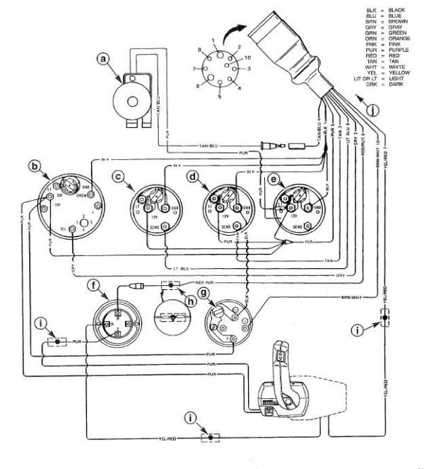
Figure 1. Tachometer terminals. Beginning with the tachometer, Fig. 1 here shows the back of a typical gauge. At the top left of the diagram, we see the cylinder selector switch. Most vendors will use one tachometer head to cover a variety of engines. Make sure this switch is set to the number of cylinders for your engine.

Mercury Outboard Gauge Wiring Diagram
How to Wire a Fuel Gauge in a Boat? Last Updated on October 1, 2022 Installing a new fuel gauge in your boat can seem like a daunting task, but it is actually quite simple. The most important thing to remember when wiring a fuel gauge is to never connect the ground wire to the sender terminal.
[DIAGRAM] Faria Boat Gauges Wiring Diagrams Diagram
A wiring diagram is an essential tool for any boat owner when it comes to understanding the inner workings of their vessel. Understanding a wiring diagram can help you troubleshoot or diagnose electrical problems and make sure all components are connected properly. Boat gauge wiring diagrams provide you with the necessary information to connect various […]

Boat Tachometer Wiring
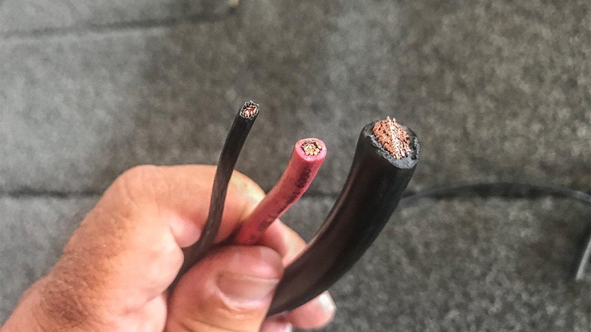
Sizing of individual conductors is based on three things: (1) how much amperage the circuit is going to have running through it, (2) whether the cable is routed through a hot engine room space, and (3) the temperature rating for the cable insulation.

Understanding Wiring Diagrams For Fuel Gauges On Boats Moo Wiring
Step 1: Check the wiring diagram then disconnect the battery when you're ready. Step 2: Start connecting the wires to their appropriate terminals. Conclusion A Few Pointers Before You Start Wiring Let's make one thing clear first: Not every fuel gauge has the same installation setup.

VDO Gauges wiring guide DRAGON MARINE SYSTEMS
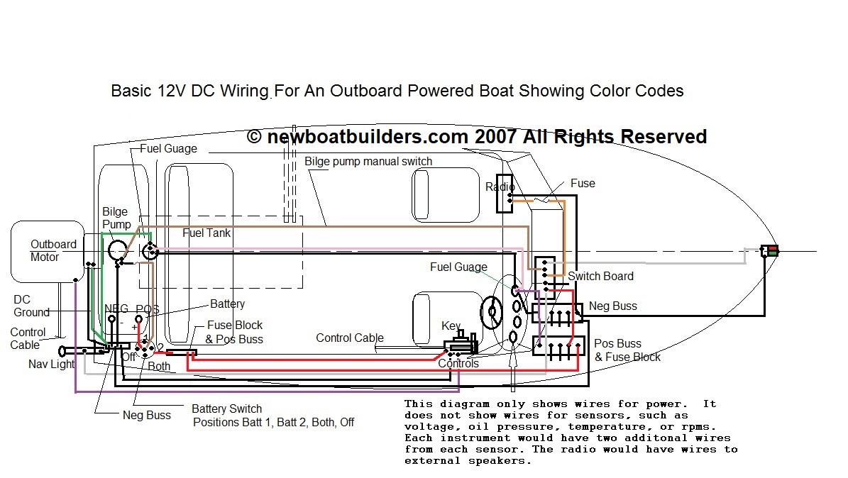
Jump To Complete Diagram Download PDF Guide 1. The Electrical Source: a Battery In a boat, electricity is stored in one or more batteries. The batteries are charged by your engine's alternator or auxiliary battery charger.
Troubleshooting Boat Gauges Soundings Online
Understanding the structure of a wiring diagram is the first step in correctly installing your boat gauges. This type of diagram shows the relationship between the various parts of the system, including the wire and the gauge. Each component is represented by a symbol, and the connections between them are indicated by lines.
wiring boat gauges diagram
371 32K views 1 year ago Pontoon Motor Rigging & Gauges DON'T BE AFRAID TO WIRE YOUR OWN GAUGES! We're breaking down the basics of what's happening behind the dash on your console with your.
boat gauge wiring diagram
Your diagram should have one line for those three enclosed wires, except as necessary to differentiate them at the ends. The wiring colors on your boat may be very different, especially if it's older and there's been a lot of "jury rigging" in its past. Make no assumptions about which wires do what.
Omc Tachometer Wiring Diagram Wiring Diagram
Draw a square, label it with the name of the device (inverter, switch) and show the wires that are connected to it. For DC wiring, positive wires are red, negative wires are yellow (or black in some cases). Your boat wiring system should have a marine grade main battery disconnect switch which allows you to open the switch to turn everything.

Basic Boat Wiring Diagram Electrical Systems
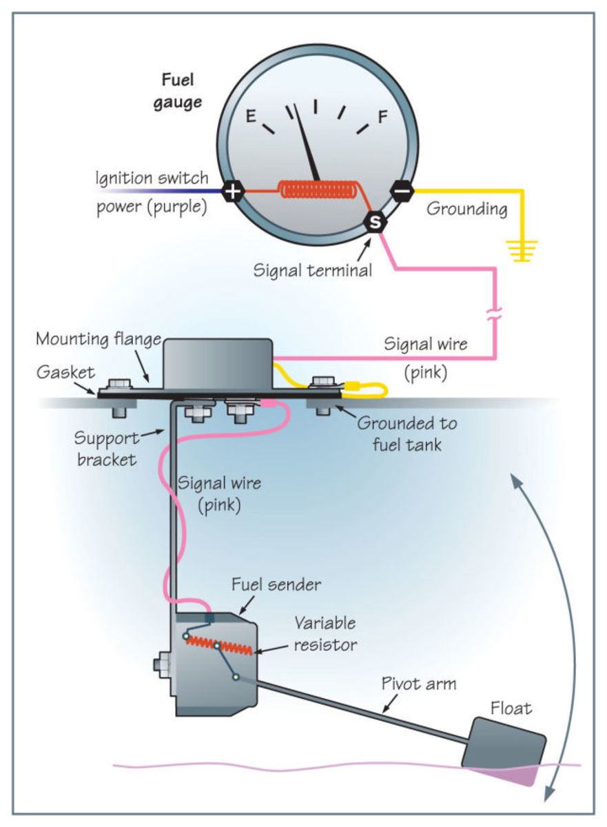
The fuel gauge then displays this information on the instrument panel. When it comes to boat fuel gauge wiring, all of these components must be wired correctly in order for the fuel gauge to function properly. This means running a wire from the fuel sending unit to the fuel gauge. Depending on your boat, this may involve some custom wiring.

Yamaha Outboard Tachometer Wiring Diagram Wiring Diagram Schemas
This will help in planning the equipment you need, wire lengths and key connections in your boat wiring. We have included several layout boat wiring diagrams (including a basic boat wiring diagram, a 2 battery boat wiring diagram, a full spec small boat wiring diagram and a Jon boat wiring diagram), at the end of this article.

Wiring Diagram For Boat Gauges Wiring Digital and Schematic
The wiring diagram for a boat fuel gauge typically consists of a few basic symbols. The most common symbols are C (for common), S (for send), R (for receive), and P (for power). By looking at the diagram, you can easily identify which wire goes to which part of the gauge. In addition, the diagram also includes information about the power.
Basic Electrcity How to Wire The Eletrical System On Your Boat
Turn on the engine's ignition and probe with a multimeter between the ground and the positive terminal on the back of the gauge; it should be marked with a "+" or an "I." If there is no voltage then the fault is in the ignition circuit—and the gauge is probably good.
