Introduction to Arduino Uno The Engineering Projects

Arduino Uno Circuit Diagram Wiring Digital and Schematic
The schematic diagram for the Arduino Uno R3 is an essential tool for understanding how the various components of the board are connected and work together. It provides a visual representation of the electrical connections between the different parts of the circuit.
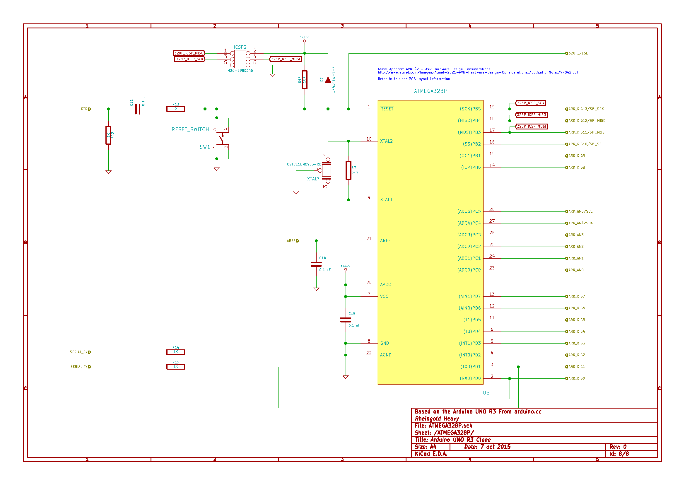
Arduino Uno Atmega328 Circuit Diagram Wiring View and Schematics Diagram
Temperature, Relay, Motion, Touch, GPS, CAN and Much More. Huge Range of Microcontroller Sensor Modules and Interface Boards

Circuit Notes Arduino Uno
Arduino UNO is a microcontroller board based on the ATmega328P. It has 14 digital input/output pins (of which 6 can be used as PWM outputs), 6 analog inputs, a 16 MHz ceramic resonator, a USB connection, a power jack, an ICSP header and a reset button.
arduino uno schematic diagram
The 5 Best Free Schematic Drawing Software for Arduino and Raspberry Pi You can find countless free circuit diagram drawing options online for both Arduino and Raspberry Pi. This type of software comes in many forms, making it crucial that you take the time to explore your options before you get started.

Circuit Diagram For Arduino Uno
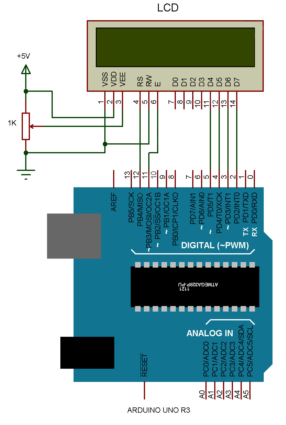
Here is a schematic for the Arduino, with all of the digital, analog and power and ground pins labelled with their numbers or function, placed next to a drawing of the Arduino Uno for comparison. Don't worry about memorizing the pin numbers and functionality now, we will explain more about the pins and their uses later on.
What is Arduino Uno Hardware Board? Everything you need to know about the Arduino Hardware
Here the Arduino UNO schematic diagram (click to enlarge): About Arduino UNO: The Arduino Uno is really a microcontroller board based on the ATmega328.
Wiring Diagram Arduino Uno Wiring Diagram and Schematics
The Arduino Uno pinout consists of 14 digital pins, 6 analog inputs, a power jack, USB connection and ICSP header. The versatility of the pinout provides many different options such as driving motors, LEDs, reading sensors and more. In this post, we'll go over the capabilities of the Arduino Uno pinout. Start Your Arduino Circuit

Circuit Diagram Of Arduino Uno Atmega328
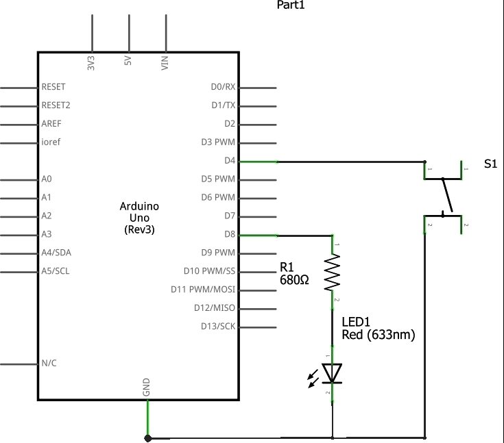
The Arduino Uno board is the main component of the circuit diagram and serves as the microcontroller. Jumper wires are used to connect the different components together. LEDs are used to indicate the status of the circuit. Resistors are used to limit the current flowing through the LEDs.
Arduino uno schematics portallopez
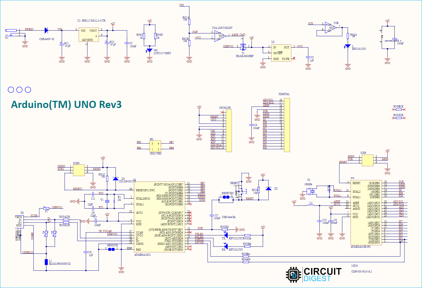
Redistributed version of the original Arduino schematic. Click to enlarge. Arduino_UNO_R3.zip The Microcontroller

Schematic diagram of Arduino UNO board connected with HCSR04 and LM35... Download Scientific
The following Arduino Uno schematic diagram can be opened and forked in Flux so that you can create your own custom layout! This allows you to modify the position of components while maintaining the same pinouts. Components of the Arduino Uno

Schematics of the connections between Arduino® Uno board with the... Download Scientific Diagram
(adc5)pc5 28 (adc4)pc4 27 (adc3)pc3 26 (adc2)pc2 25 (adc1)pc1 24 (adc0)pc0) 23 (sck)pb5 19 (miso)pb4 18 (mosi)pb3 17 (ss)pb2 16 (oc1)pb1 15 (icp)pb0 14 (ain1)pd7 13 (ain0)pd6

Arduino Uno R3 Schematic True Diary
Arduino reserves these for future definition and shall have no responsibility whatsoever for conflicts or incompatibilities arising from future changes to them. The product information on the Web Site or Materials is subject to change without notice. Do not finalize a design with this information. VIN. +5V CMP. +3V3. 3 U1A.

Arduino Uno Schematic (Colour) Embedded Electronics Blog
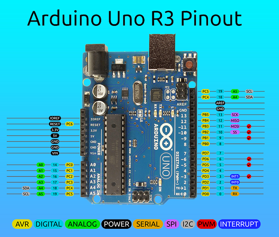
Arduino UNO R3 pin diagram shows that it has 6 analog inputs, 14 digital input/output pins (of which 6 can be used as PWM outputs), a 16 MHz ceramic crystal resonator, a USB-B port, an ICSP header, Atmega328p and Atmega 16U2 processor, a power jack and, a reset button. Arduino UNO pinout Arduino UNO R3 Pin diagram (Official)

Arduino Uno Schematic Diagram A Comprehensive Guide
Here we have the schematic diagram of the latest revision of Arduino UNO. Don't worry if you can't see it much right now. We'll chop it up after and analyze every section according to their function. Here we can visibly identify each component on board, besides the obvious Atmega328P.

Understanding Arduino UNO Hardware Design Technical Articles
Here the Arduino UNO schematic diagram (click to enlarge): About Arduino UNO: The Arduino Uno is really a microcontroller board based on the ATmega328. It has 14 digital input/output pins (of which 6 may be employed as PWM outputs), 6 analog inputs, a 16 MHz crystal oscillator, a USB connection, a power jack, an ICSP header, along with a reset.

Arduino UNO Pinout Diagram Microcontroller Tutorials
The Arduino Uno schematic diagram contains a variety of components, including power sources, switches, ICs, transistors, and diodes. Here is a brief overview of some of the components that appear on the Arduino Uno schematic diagram: Power Sources: Power sources provide electricity to the circuit.
